WHITE PAPER
Spend Less Time Making Better Fiber Measurements
Download PDF
Overview
The Telecommunications Industry Association, in TIA 568.3-D has defined a two-tier certification process that not only certifies compliance with cabling standards but also optimizes the installation quality by identifying marginal components. ANSI/TIA 568.3-D uses the terms “Tier 1” and “Tier 2” while IEC 14763-3 uses the terms “Basic” and “Extended” Test Groups:
- Tier 1 / Basic Tests measure performance of the overall channel/permanent link and can be performed using a light source and power meter (LSPM) or an automated Optical Loss Test Set (OLTS).
- Tier 2 / Extended Tests add measurements that evaluate components within the channel and require an Optical Time Domain Reflectometer (OTDR).
Tier 2 complements Tier 1 for a very simple reason: Tier 2 is more detailed but is more uncertain than Tier 1. At first this might sound like an oxymoron but it results from fundamental technical principles, true for OTDRs whether past or future models. In fact, OTDR's can deliver accurate measurements, but in order to do so, proper techniques must be employed – techniques that are all too often bypassed for being too complex. This paper describes new methods and procedures that deliver more correct and repeatable results and, at the same time, significantly reduce the overall testing time.

On This Page
OTDR’s Have A Point View
We will now take a step back and describe various OTDR test scenarios as they typically occur today. Measuring the loss of individual events, such as connectors and splices, as well as the overall link loss unfortunately depends on the direction from which the measurement is made. Even though you won't find the term on Wikipedia, we will call this “Directivity”.
“Directivity” results from differences in diameter, backscatter, numerical aperture and index of refraction of the link under test as well as the launch and tail fiber. In singlemode fiber, directivity is influenced by differences in backscatter coefficients between different fibers. In multimode fibers, core diameter and numerical aperture play a bigger role.
One of these directivity effects, differences in backscatter coefficient, can be removed through bi-directional testing. If the fibers on either side of a connector have different backscatter coefficients, the connector will appear to have greater loss when tested in one direction than it does when tested in the opposite direction.
In this example, the phase #1 measurement for the first connector shows a “negative loss” (-0.05 dB), a phenomenon known as a “gainer”. As the name implies this indicates the signal increases as it goes through the connector, an impossibility that is typically an artifact of a difference in the backscatter coefficient between the two cables. When tested from the other direction (phase #2), the loss measures 0.35 dB. The actual loss is the average of these two measurements or 0.15 dB.
In order to get to the correct loss values we need to average the results from the two measurements that were performed from End 1 and End 2, see Figure 1.
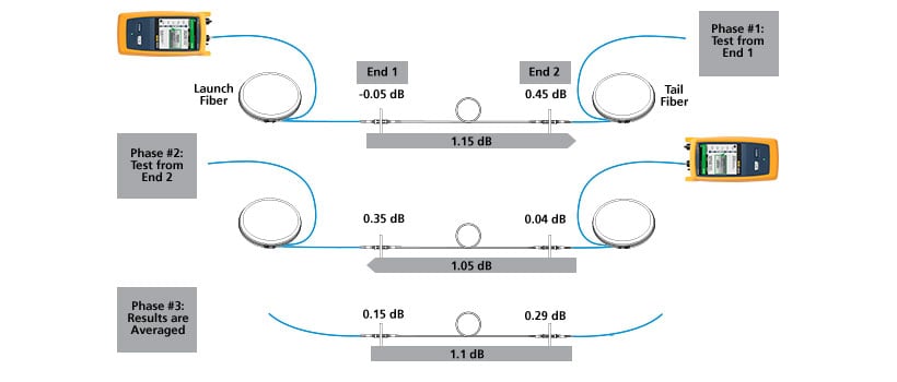
Figure 1: For the leftmost connection, we need to average -0.05 dB and 0.35 dB which results in a true loss of 0.15 dB. Note that the measured result for the fiber itself remains 0.66dB regardless of the direction of measurement.
A Reality Check
While the above method delivers the most correct measurements for OTDR-based loss testing it does come at a price. It requires a 2-step measurement process and a partner at the far end who moves the tail fiber to the next port when testing from patch panel to patch panel. Since this type of testing is very time consuming, installers are tempted to take a short cut and test without the use of a tail fiber. (Note that in this method, the launch fiber is usually moved with the tester, which is in violation of all testing standards and will lead to additional measurement errors beyond those documented here.)
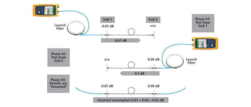
Figure 2: Bi-Directional Test without a Tail Fiber (same link as in Figure 1).
| Methodology | Conn. #1 | Conn. #2 | Overall |
|---|---|---|---|
| Launch & Tail Fiber (Figure 1 – averaged) | 0.15 | 0.29 | 1.04 |
| Launch fiber only (Figure 2) | -0.05 | 0.04 | 0.65 |
| Error (Expressed as a percentage) | 133% | 86% | 36% |
Table 1: Error Analysis Testing without a Tail Fiber
OTDR Testing With A Loop
The above problem is not a surprise to experts and a procedure named “Looped OTDR testing” was developed and is increasingly required by systems designers.
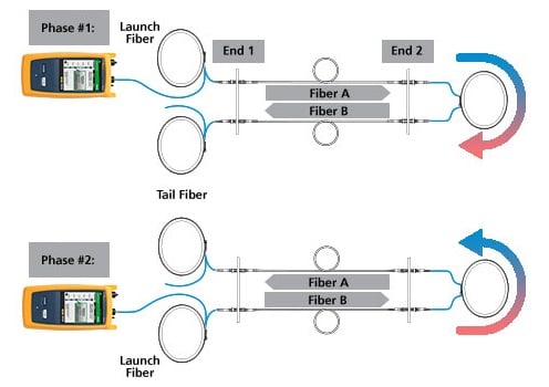
Figure 3: Bi-Directional Test
By using a loop at the remote end, which has a length similar to a launch or tail fiber, the two fibers of a duplex link – Fiber A and Fiber B – can be tested in one shot and phase two of a bi-directional test can now be performed without moving the OTDR to the other end. The only disadvantage of this loop-based test using a traditional OTDR is that it requires extensive manipulation by the user to extract the individual link specific data after the traces are obtained.
Testing with a “SmartLoop™ Assistant”
An OTDR with a built-in “SmartLoop Assistant” can convert the very cumbersome and error prone manual loop process into an automatic test whilst maintaining all the advantages of a loop-based OTDR testing process. Table 2 highlights the advantages of SmartLoop Testing.
In many cases technicians take the launch fiber together with the OTDR to the other end of the link when they perform a bi-directional test. This is fundamentally wrong and defeats the purpose and benefit of performing a bidirectional test. Both the launch and tail fibers used in bi-directional tests must stay in place during tests in both directions. Figure 4 shows how the animated screens of the SmartLoop-Assistant help prevent this common mistake.
OTDRs are often operated by novice users and the SmartLoop Assistant will ensure that no incomplete traces are taken. This eliminates the need to go back on-site to re-take a trace.
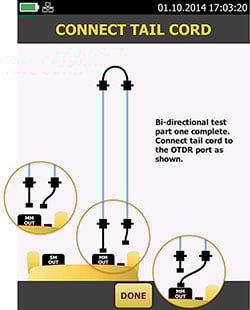
Figure 4: Animated screens lead the user through the correct testing methodology.
In Figure 5 we see that the SmartLoop Assistant checked for the presence of a Launch-, Loop- and Tail Fiber, as well as that Fiber A and B are in the right order and that they have the expected length.
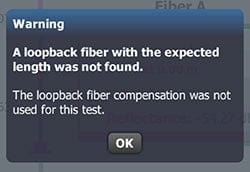
Figure 5: The SmartLoop Assistant warns the user when not all expected elements are found.
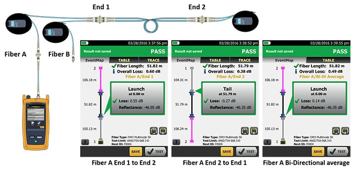
Figure 6: SmartLoop measures each fiber in both directions and then computes an averaged result for each. Users can change views by using the two buttons on the lower right of the screen. Shown (left to right): Fiber A end 1 to end 2; Fiber A end 2 to end 1; Fiber A averaged result.
After finding all the expected elements the SmartLoop Assistant generates six test records: both fibers in both directions and then an averaged result for each fiber. The user can easily switch between the different views, see Figure 6.
A single tech can perform SmartLoop tests quickly and efficiently with a relatively small investment in additional loop fibers as shown in figure 7. Loop fibers are placed on the right hand ends of the fibers. Next, the tech moves to the left hand side and performs SmartLoop tests on each fiber pair with a loopback. The tech then moves to the right side, and moves the loop fibers to the next set of fibers to be tested and the process repeats. This can be nearly as fast as the "no tail fiber" method above, but is much more accurate.
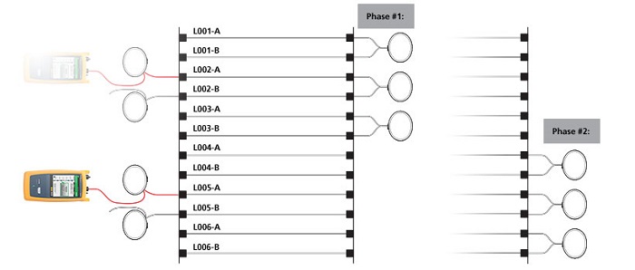
Figure 7: Multiple loops allow a single technician to perform a set of bi-directional tests before walking to the other end or calling for assistance.
Customer Comments
![]() Integrity Networks, based in Renton, Wash. provides communications services and infrastructure installation for cable and fiber networks nationwide and around the Pacific Rim. Its Anchorage-based Alaska Branch office and technicians were working on a significant job for an energy company that required the company’s techs to test over 1,400 fiber links bi-directionally. The task was further complicated by winter weather, so the temperature and environmental considerations made it challenging and even dangerous to travel between buildings to perform tests at both ends of the fiber.
Integrity Networks, based in Renton, Wash. provides communications services and infrastructure installation for cable and fiber networks nationwide and around the Pacific Rim. Its Anchorage-based Alaska Branch office and technicians were working on a significant job for an energy company that required the company’s techs to test over 1,400 fiber links bi-directionally. The task was further complicated by winter weather, so the temperature and environmental considerations made it challenging and even dangerous to travel between buildings to perform tests at both ends of the fiber.
“When I saw SmartLoop, I thought it would be the perfect answer to our challenge. Once we got it, our team was able to master the OptiFiber Pro operation quickly,” said Randy Sherman, Alaska Area Manager for Integrity Networks. “And by using SmartLoop, we cut the total costs of testing by more than 30 percent. In fact, the savings on our first job paid for the tester.”
![]() Twistnet Communications Ltd serves companies in the United Kingdom and Europe with core services and it offers experts in fusion splicing, direct fiber termination, OTDR and power-meter testing and certification and repair. On one major project, Twistnet Communications was called on to bidirectionally test 400 links inside a high voltage electrical substation located in an offshore wind farm. Working in this environment requires a full Health and Safety (H&S) induction which can cost upwards of £500.00 per person.
Twistnet Communications Ltd serves companies in the United Kingdom and Europe with core services and it offers experts in fusion splicing, direct fiber termination, OTDR and power-meter testing and certification and repair. On one major project, Twistnet Communications was called on to bidirectionally test 400 links inside a high voltage electrical substation located in an offshore wind farm. Working in this environment requires a full Health and Safety (H&S) induction which can cost upwards of £500.00 per person.
“With the capability of SmartLoop we were able to borrow a wind farm technician who could take the place of one our technicians inside the substation. Twistnet Communications provided the wind farm technician with quick training on use of installing a loopback lead and what would be required to test each link bi-directionally. Communicating by walkie-talkie, Twistnet technicians walked the wind farm technician through moving the lead and testing each link bi-directionally.”
“We were able to save about four man days and more than £2,000 working onsite using SmartLoop on this one project,” said John Marson.
“Importantly, we can cut down on testing time with SmartLoop, which is a benefit for winning projects,” stated John Marson. “We have probably won 20 contracts since we started using SmartLoop for testing and certification.”
Summary
With growing pressures on profitability, installers and contractors want to get the job done quicker and above all “right the first time”. This requires innovative testing capabilities such as the automatic SmartLoop, to simplify tasks and reduce the time spent testing. Not only does it cut test time by at least 50%, it also greatly eliminates the need to have an additional technician permanently stationed at the far end when performing bi-directional OTDR tests, and last but not least it helps to prevent the most common but fundamental mistakes.
| Issue | Pros & Cons | Manual Loop | Automatic Smart Loop |
|---|---|---|---|
| 1 | + Reduces Testing time by 50% | ✓ | ✓ |
| 2 | + No need to walk OTDR to the other end | ✓ | ✓ |
| 3 | + Lifetime of Launch & Tail Fibers gets doubled because after single mating two links are tested in both directions and the wear is spread to both end of the of Launch & Tail Fibers | ✓ | ✓ |
| 4 | + Allows bi-directional test in case of restricted or dangerous access to one of the two ends (GSM Towers, Wind Towers, Elevated Stations in factories, Highly secure Data Center Zones, etc.) | ✓ | ✓ |
| 5 | − Time consuming post process to: Identify A and B segment and create two distinct records | ✓ | |
| 6 | − Manual post processing by the user increases the risk of error | ✓ | |
| 7 | − Handling of “Zero’ed” (due to directivity) APC connectors very difficult | ✓ | |
| 8 | + The fiber segment A and B is identified automatically and saved as two records | ✓ | |
| 9 | + No additional source of error due to manual cursor setting | ✓ | |
| 10 | + Automatic handling of “Zero'ed” APC connections | ✓ | |
| 11 | + On screen wizard assists user in the correct execution of the bi-directional testing process | ✓ | |
| 12 | + Automatic assistance check for the presence of Launch-, Loop- and Tail-Fibers | ✓ |
Table 2: Advantages of OTDR testing with a loop fiber
OptiFiber® Pro OTDR – built for the Enterprise
 Fluke Networks' OptiFiber® Pro is the industry's first OTDR built from the ground up to meet the challenges of enterprise fiber optic infrastructures. OptiFiber Pro OTDR's ultra-short dead zones facilitates the identification of fiber patchcords in virtualized data centers. SmartLoop™ technology enables the testing of two fibers in both directions, and averages the measurements as required by TIA-568.3-D in seconds – without taking the OTDR to the far end.
Future-ready design supports Cat 5e to Cat 8 certification, singlemode and multimode fiber loss plus inspection. Integrates with LinkWare™ Live to manage jobs and testers from any smart device.