DC Loop Resistance Measurement and Testing
DC Loop Resistance is the total resistance through two conductors looped at one end of the link. This is usually a function of the conductor diameter and varies only with distance. This measurement is sometimes done to ensure there are no gross misconnections which can add significant resistance to the link. Note that the wire map test automatically isolates breaks but not high resistance connections.
DC resistance is often confused with impedance, a term describing the dynamic resistance to signal flow, usually at a specified frequency. Both are measured in ohms because they define different types of opposition to electrical current flow. DC resistance increases proportionately with the length of the cable tested while impedance remains "fairly" constant regardless of length.
From a signal perspective, attenuation (sometimes called insertion loss) is now a more useful measurement, and DC resistance has become less important. Well, not quite with VoIP becoming popular which provides power over the cable.
Results Interpretation
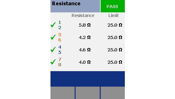
Variations in loop resistance between pairs can often be a quick indication of a cabling problem. In a shorted loopback test environment, the expected value is simply twice the sum of the value expected for the given length. This is a simple test for any advanced field tester.

The values will be different for each pair combination, due to the different twist rates between the pairs. Looking at the above result, we could conclude that the 1,2 pair has the tightest twist and 7,8 has the least twist. This is normal and to be expected.
Troubleshooting Recommendations
In the case of unexpected high DC resistance, compare the failed pair against other pairs in the cable. This will determine whether the issue is specific to the one failed pair or due to a problem affecting the entire cable. If a single pair is at fault, inspect termination points for a poorly made or oxidized connection.
If all four pairs have unexpected high DC resistance, check your assumptions. Did you allow for double the resistance to include the loopback? Is the resistance assumption correct for the gauge of wire used? 26 gauge has higher resistance per foot than 24 gauge. Do you have an unusual patch cord in the link that could have high resistance? Look for anything unusual especially if adjacent cables appear to be normal.


