Certifying MPO Singlemode links with the CertiFiber Pro
This article describes a method for certifying Single Mode links with 8, 12 and 24 fiber pinned or unpinned MPO connectors at each end using the CertiFiber Pro.
Since this method requires the use of break out cables or cassettes (LC to unpinned MPO), the user needs to understand the desired polarity for their installation. Using the MultiFiber Pro will result in a quicker certification. Additionally, the MultiFiber Pro automatically reports polarity.
You will need:
- CFP2-100-S or CFP2-100-Q Fluke Networks Certifiber Single Mode or Quad
- SRC-9-SCLCAPCKIT-M Quantity 1 – Test reference cords for Single Mode LC/APC connectors
- LCAPC to LCAPC reference grade patch cord Quantity 2 – no Fluke Networks part number
- Duplex LC bulkhead adapters (Singlemode) Quantity 4
-
Uninned MPO to LC break out cable SBKC-MPOAPCU-LCAP Quantity 2 - from the cabling vendor you are testing
- Alternatively, you can use a break out cable with gender changing connectors and test either pinned or unpinned links
- Alternatively, you can use an MPO/MTP cassette (which is a break out cable in a small box)
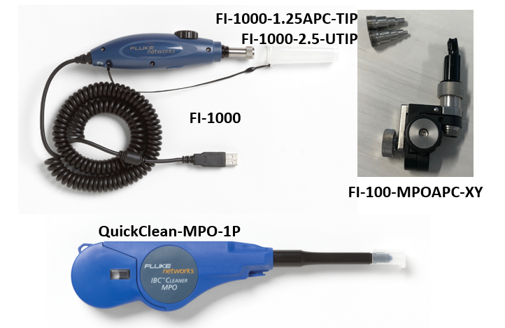
Additionally, inspection is critical for this method to work. Without inspection, you may end up with pessimistic results. Inspection includes both the end faces of the MPO and LC connectors. MPO adapter tips are available for the USB FI-1000 FiberInspector which attaches to your Versiv. Or you may use FI-3000 for MPO endface inspection. Don’t forget a cleaning kit.
- FI1000 -- Inspection Camera
- FI1000-1.25APC-TIP – LC APC patch cord inspection tip
- FI1000-LCAPC-TIP – LC APC inspection tip for camera (Optional as needed)
- FI1000-MPOAPC-XY – MPO Inspection tip for camera
- Or Use FI-3000 for MPO Inspection
- QuickClean-MPO-1P – MPO Cleaner
- QuickClean-1.25-1P – LC Cleaner
-
Ask your cabling vendor/consultant for their test limits. Here we shall use TIA-568.3-E Multimode with a 3 Jumper Reference. You may have been told; "Never carry out a 2 or 3 Jumper Reference for link testing.”
However, for testing cables with a connector you don’t have on your power meter, like an MPO or an MTRJ, a 3 Jumper Reference is required. -
First, we are going to set up to do a 1 jumper reference, this will allow us to use the Set Ref Wizard.
- Inspect all cords before connecting them. Clean if necessary. Inspect again after you clean before connecting them.
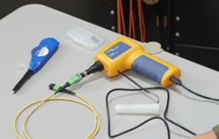
- Insert the SC to LC APC TRCs into the output ports of the main and remote units.
- Connect the Versiv Main and Remote units together.
-
From the HOME screen, tap SET REF > RUN WIZARD > NEXT
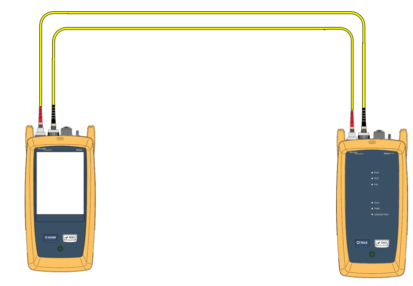
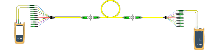
Connect the cables as shown in the diagram and SET REFERENCE. -
Follow the step in the Wizard to set the reference and Verify the Test Reference Cords (TRC). Be sure that you have a loss value with the TRC of less than 0.25 dB. When following the Wizard, the TRC verification will be automatically saved.When you finish the wizard, press HOME.
-
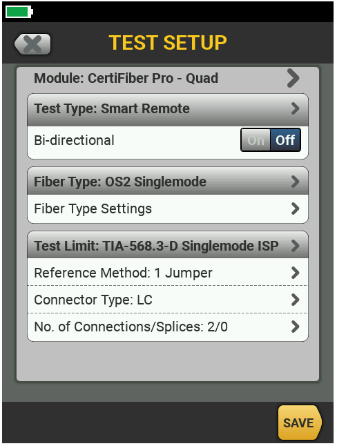
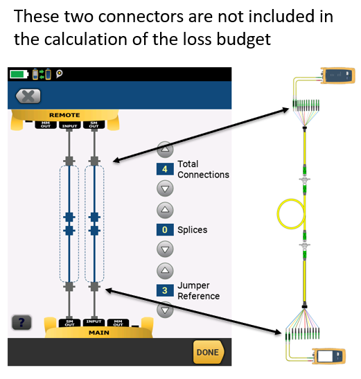
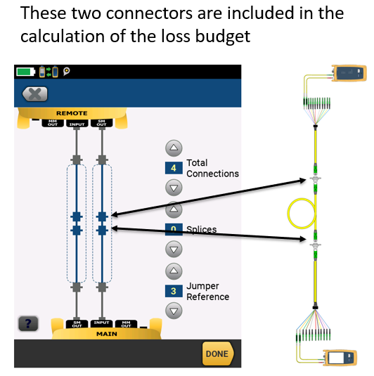
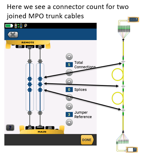
Go back into the test set up and select a 3 jumper reference. You will need to count the total number of connections that you have in your link including the test cords. Since we are going to ‘reference out’ the LC connections to the fanout cables, these two connectors will appear ‘outside the box’ on the setup screen.
-
Now that you have the correct connector count for the loss budget calculation, return to the HOME screen and go to SET REF. With a 3 jumper reference selected, the SET REF Wizard will start with a 2 jumper reference that we have currently set up. Follow the steps in the Wizard to set the reference and to verify the 3rd jumper TRC.
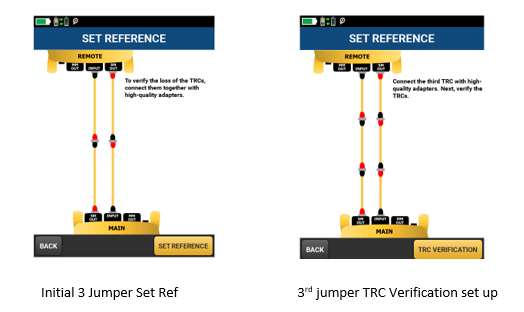
- Make sure that you have a loss value of less than 0.25 dB for the TRC verification. The tester will warn you if you do not. If you do not, inspect and clean the connectors as needed and re-verify the TRC until you get less than 0.25 dB. This is important, and we will look for this in the test results to assure you are testing correctly. When you run the Wizard for TRC verification, it saves the result of that test along with your other test results.
-
Remove the third jumper, the one in the middle. Inspect the LC connectors of the MPO fan out cable and attach the MPO fan out, or MPO/LC cassette, to both ends.
- Inspect the MPO/MTP connectors and clean if necessary. Now connect the MPO trunk cable to be tested.
-
Test the LC connectors on both ends and go through the connectors. Depending on the polarity of the MPO trunk, you may need to switch the position of the Test Reference Cords.
Additional Information
- Try this in your office to make sure you are comfortable with the procedure first.
- Ensure you lay out the cables when setting a reference, avoid coils in the cable.
- Re-verify the test reference cords every 500 tests, per steps 5-7 above. The results of the re-verification should be recorded.
- LC connectors are rated at typically 500 insertions.
- MPO connectors are rated between 500 and 1000 insertions - check with your vendor. (Assumes you are connecting into clean connectors)