-
Originally developed at the Xerox Palo Alto Research Center (PARC) in the 1970’s Ethernet has grown to become the world’s most common networking system. Over the intervening decades, tremendous changes and extensions to the standards have allowed Ethernet to address a wide variety of applications that were never envisioned by the original developers.
One of these applications is Industrial Ethernet. Vendors and standards organizations have adopted the underlying physical layer of Ethernet to create a variety of technologies, such as PROFINET, Ethernet/IP (Industrial Protocol), EtherCAT, and Modbus-TCP, which are optimized for industrial automation.
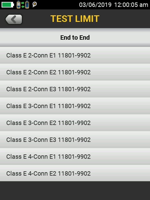
Figure 1. DSX CableAnalyzer™ screen displaying test limits for different end-to-end cable configurations including E1, E2, and E3 limits.
Cabling Standards and Connectors
All Industrial Ethernet applications are designed to work on twisted pair copper or fiber cabling similar to that used in “regular” Ethernet, with some modifications for the factory environment. The International Standards Organization (ISO) and the Telecommunications Industry Association (TIA) developed a set of specifications to define potential environmental conditions within industrial sites. These are known as the Mechanical, Ingress, Climatic/Chemical, Electromagnetic (MICE) specifications. MICE levels describe various degrees of environmental conditions, with MICE 1 defining a typical office environment, MICE 2 defining a slightly harsher environment, and MICE 3 defining heavy industrial.
To meet these requirements, vendors have developed specialized cabling and connectors. This includes cabling which can operate while being crushed, heated, immersed, or exposed to caustic chemicals. In most cases, this affects the requirements for the outer jacket of the cable, while the electrical characteristics remain the same whether it’s MICE 1 or MICE 3. However, one notable difference is found in the Electromagnetic requirements, where specific requirements for Transverse Conversion Loss (TCL) are specified for E1, E2, and E3. This specification measures the ability of the cable to resist interference from outside electrical signals such as those generated by welders, variable speed drives, and high voltage power.
Connectors get special scrutiny as they can be a point of ingress. One approach is to encase the standard 8-pin modular connector (RJ-45) in a sealed, screw-on receptacle. This connector has the advantage of being compatible with most “regular” Ethernet devices and cabling. The “M12” connector was developed for more stringent shock and vibration applications, and features a small, round locking screw type connector which can include two pairs (M12-D), or four pairs (M12-X). A common industrial cabling configuration will include a modular 8-pin connector on one end of the cable connected to a M12 connector on the other.
Cabling Problems
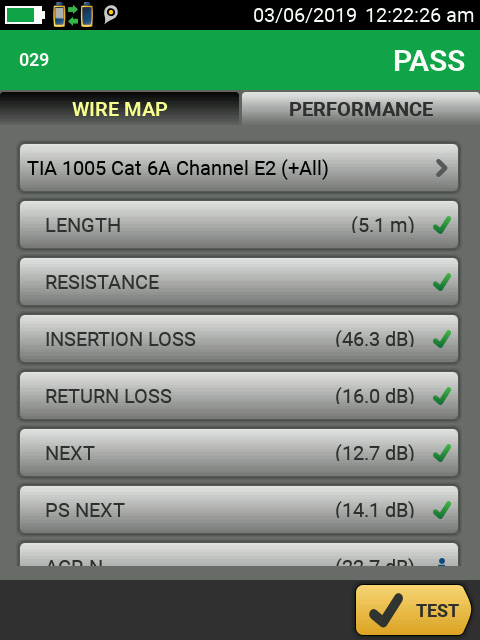
Figure 2. DSX CableAnalyzer display showing passing test results for a TIA 1005 Category 6A link with E2 limits.
More than half of Industrial Ethernet problems can be traced to cabling. Some of these show up immediately during the startup process – others can allow the connection to function properly until something such as environmental changes cause communications failures. Ethernet is a robust technology that allows communications to continue even under marginal circumstances – but a change in those circumstances might cause communications problems or a complete failure down the road. Here are the most common problems with cabling.
Connectivity
The most basic requirement for cabling is that the pins on one end are connected to the correct pins on the other end. Any miswiring or opens in the cabling will cause a hard communications failure. A less well-understood wiring problem is what is called a “split pair”, when the pins are connected through to the appropriate ones at the other end, but the cable pairing is incorrect. This can lead to intermittent or hard failures.
Length
In general, Ethernet cables are limited to 100 meters in length. Cables that are too long can cause problems in two ways. First, the signals weaken as they travel over a cable – if it’s too long, they might be too weak to be received properly at the far end. Second, Ethernet is designed to expect responses within a certain timeframe – the delay caused by a cable that is too long can interfere with this timing. Either of these errors can lead to hard failures or intermittent problems. For example, since the loss of a cable increases with temperature, a too-long cable may transmit acceptably at lower temperatures yet fail at higher ones.
Crosstalk
This is a measurement of the electromagnetic interference between pairs within a cable. For example, a signal transmitted on the “send” pair could be generate an interfering signal on the receive pair. The transmitter could interpret this interference as an incoming signal and stop sending. Again, this can cause either hard or intermittent failures. As signal frequencies increase, so does crosstalk, making it the major determinant of the maximum performance of a network cable.
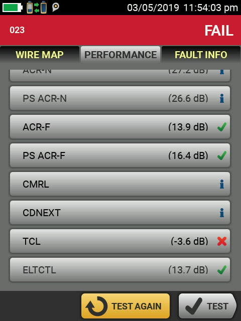
Figure 3. DSX CableAnalyzer displaying results of a failed E3 level test. Note the TCL failure.
Shield Integrity
Many Industrial Ethernet cables incorporate a shield – typically a metallic foil that encases each pair inside the outer cable jacket. The purpose of this shield is to reduce the effect of outside Electromagnetic Interference (EMI), which can come from high voltage or high current devices near the cable. EMI can cause transmission errors on the cable, resulting in slowdowns or even complete failures. This can be a very difficult problem to troubleshoot, as it will only occur when the interference is great enough to overcome the signal balance, such as when a nearby motor starts up or a welding tool is used. For the shield to work effectively, it’s critical that the cable be shielded along the entire path – even one break in the continuity of the shield can greatly diminish its performance. Therefore, tests of the shield must be able to ensure that the entire path of the cable is shielded. This is a particularly difficult measurement as the shield is typically grounded. Simple DC measurements will not be able to determine if the shield is continuous if it is grounded at both ends.
Transverse Conversion Loss (TCL)
This is a measure of the “balance” of the cable – its ability to transmit equal signals on both wires of a pair. Twisted-pair cables achieve a high level of noise immunity by relying on the differential between equal but opposite signals on the two wires within a pair. If the cabling causes the signals to be unequal, external noise can cause interference with the signals and distort them to the point that they cannot be recognized by the receiving device. As noted above, EMI problems can be very difficult to isolate and solve. To address this problem, standards bodies have developed TCL requirements for cabling for MICE E1, E2, and E3 environments.
It's important to note that using cable and connectors that are certified by the manufacturer to meet the requirements noted above is critical to ensuring error-free operation, but it’s no guarantee. Sometimes even the best vendors can produce a off-spec product, and more commonly, improper installation techniques can turn a collection of top-quality components into a poorly-performing link.
Cable Testing Means More Uptime
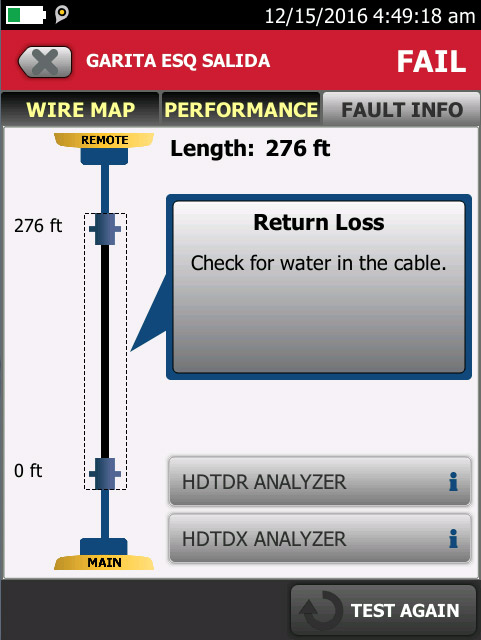
Figure 4. The DSX CableAnalyzer can find a wide variety of cabling faults and display them in a way that any tech can understand.
Organizations outfitted with the appropriate cable testing tools and a basic understanding of their use can employ them to increase their uptime, in three ways:
Faster Startup
Measuring the parameters noted above before connecting a cable is the only way to ensure that it meets all required specifications and will therefore work properly.
Prevent Unplanned Downtime
Just because a cable can pass data at startup is no guarantee that it will continue to work under all circumstances. Changes in the environment after installation can cause failures. If the cable is tested against the parameters noted above and passes, the chances of later cable failures based on these factors can be eliminated.
Solve Problems Faster
Even a tested cable can fail due to abuse such as being accidentally cut, pulled apart, or melted. In the case of a network failure, being able to diagnose a cabling problem fast can save a significant amount of time. Rather than spending hours replacing a suspect cable, a few seconds of testing can verify if it’s OK, so troubleshooting efforts can be focused elsewhere. And if the cable is bad, diagnostics in the tester can pinpoint the problem. For example, knowing that the failure is in the far end connector means you spend a few minutes replacing one bad connector rather than hours re-routing an entirely new cable.
In summary, testing cables when installed can speed the startup process and prevent problems in the future. Having a cable tester handy in the case of a failure can save hours of troubleshooting and downtime.
Cable Testing Tools for Industrial Ethernet
Cable testing tools can be divided into two categories: pre-deployment testers and troubleshooters that nest Cable and Networks.
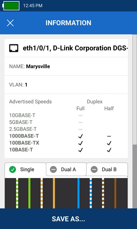
Figure 5. Cable+Network Testers, such as the LinkIQ™ can display network data including switch port, name, VLAN and speed settings.
Pre-deployment (commissioning) testers
These tools provide testing for all the cabling parameters noted above including crosstalk, shield integrity, and TCL. The DSX CableAnalyzer Series is the only cable tester that can measure all these parameters including shield integrity along the path of the cabling. The tester generates a PASS or FAIL result and can create a report for documentation purposes. Testing with a certification tool before startup is the only way to know if the cable meets all the required specifications as noted above and is the best way to prevent cabling problems. These tools may also be used for troubleshooting, and can locate not only broken cables, but more difficult problems, such as water in a cable or a connector that is not up to specification.
Cable+NetworkTesters
These tools provide the ability to test Industrial Ethernet cabling plus the active devices connected to that cabling. They verify that the cabling has been connected properly (including split pair testing) and can measure the length of the cable and identify the location of cable breaks. They can also verify the network switch they are connected to, showing port speed and Power over Ethernet and, in some cases, the switch name, port number and VLAN. This can save a lot of time by eliminating cabling or switch operation and configuration as an issue allowing the team to focus on where the problem really is.
Teams unable to invest in certification testers can still benefit from them for new projects by either renting them or hiring a cabling contractor to test the cable before start-up. The low cost of cable+network tools allows them to be kept on hand at any facility, eliminating the time required to arrange a rental or a contractor in case of a failure. Their cost is easily recovered in the time saved in resolving a single network failure.
Comparison of Fluke Networks cable testing products for Industrial Ethernet
MicroScanner™ PoE-IE LinkIQ™-IE DSX™ Series Primary Application Cable+Network Troubleshooting Cable+Network Troubleshooting Cable Installation, Troubleshooting Connectivity X X X Length X X X Crosstalk X X Shield Integrity Basic Advanced TCL / M.I.C.E. “E” Level X Reporting X X Fault Finding Basic Basic Advanced Network Tests Speed to 10 Gb/s PoE Power Speed to 10 Gb/s, Switch Name, Port, VLAN, PoE Power, Port Blink Connector Support RJ45, M12D, M12X and M8D RJ45, M12D, M12X and M8 RJ45, M12D, and M12X