WHITE PAPER
A Guide to Successful Installation of Power over Ethernet
Download PDF
Overview
Years ago, someone came up with the idea of combining power and data communications in a twisted pair cable and Power over Ethernet (PoE) was born. In the intervening years, a huge array of devices that source and consume power and data through the same cable have been launched with more coming on line all the time.

On This Page
A Guide to Successful Installation of Power over Ethernet
In most cases, using PoE eliminates the need for an AC outlet, eliminating the cost and labor of that duplicative run. It also can eliminate the separate power supply for the device, which means one less point of failure. And since PoE uses lower, safer voltages, it does not need the strict requirements, such as conduit and electrical boxes required by line powered devices.
A PoE circuit is made up of three parts:
- The Power Sourcing Equipment (PSE) which puts the power on the same cabling as the data signals. This is most typically a switch, or can also be a midspan injector used in instances where the switch is not capable of supplying power.
- The cabling which carries both the data and the data signals. The IEEE standards for PoE specify two- or four-pair twisted cabling systems.
- The Powered Device (PD), which consumes the power provided by the PSE
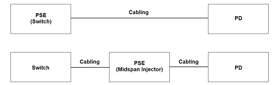
Figure 1. Basic PoE design and nomenclature
In IEEE standard implementations of PoE, power is sourced by the PSE only after it is requested by the PD. If the PD is disconnected, the PSE will remove power. This makes PoE considerably safer than typical AC power which is always present at the outlet. PoE also uses a lower voltage: 43 to 57 Vdc.
The first PoE standard, 802.3af, was adopted in 2003 and sourced up to 15.4 watts of power over two pairs. Adopted in 2005, 802.3at (also known as “PoE+”) supported up to 30 W. Cisco developed their “Universal PoE” (UPOE) using all four pairs, pushing the maximum power to 60 W. In September 2018, the IEEE approved 802.3bt, pushing the sourced power to 90 W.
| Type 3 (802.3 bt) | Type 4 (802.3bt) | |||||||
| Type 1 (802.3af) | Type 2 (802.3at) | |||||||
| PSE |
Class 1: 4 W |
Class 2: 7 W |
Class 3: 15.4 W |
Class 4: 30 W |
Class 5: 45 W |
Class 6: 60 W |
Class 7: 75 W |
Class 8: 90 W |
| 2-pair only (Type 1 & 2) | Always 4-pair power | |||||||
| 2-pair or 4-pair (Type 3 & 4) | ||||||||
| PD |
Class 1: 3.84 W |
Class 2: 6.49 W |
Class 3: 13 W |
Class 4: 25.5 W |
Class 5: 40 W |
Class 6: 51 W |
Class 7: 62 W |
Class 8: 71.3 W |
| PoE+ | PoE++, UPOE | |||||||
Figure 2: PoE classes, types and standards.
A successful PoE implementation is a three-step process:
1. Equipment selection
2. Cable certification
3. Installation and troubleshooting
Let’s look at what’s required in each step.
1. Equipment Selection
While PoE provides a great opportunity, there is a significant issue around standardization. The term “PoE” is not registered, and any vendor can claim PoE capabilities. There are currently three approved (802.3af, at and bt) IEEE standards. These standards define eight different wattage levels or classes, which can be delivered via four configurations: Type 1 and 2 which use two pairs and Types 3 and 4 which use four pairs. Further, vendors have adopted some terms, such as PoE+ and PoE++ as well as Cisco’s Universal PoE (UPOE). And while these approaches all fit within the three IEEE standards, there is further confusion with vendors creating other PoE implementations that are outside of the standards. For example, “passive” PoE implementations provide “always on” power which is not negotiated between the PSE and PD. Other implementations negotiate power levels in higher layers than the LLDP protocol. Techs in the field and even designers can become quickly confused about what will work with what. Not surprisingly, a study of over 800 installers, integrators and end users found that four of five respondents experienced difficulties in integrating PoE systems.
Ethernet Alliance Certification Program
To cut through this confusion and enhance interoperability, the Ethernet Alliance, a consortium of manufacturers representing providers of ninety percent of PSE switching equipment, has announced a PoE Certification Program. This program provides a methodology for certifying their products for interoperability with other IEEE-802.3-based PoE solutions and provides simple labeling of such products.
Certification of the products is defined by a 300-page test plan, using approved equipment. This may be conducted by manufacturers or third parties, such as the University of New Hampshire's Interoperability Laboratory (UNH-IOL). Both PSE and PD equipment may be certified. Equipment that passes this rigorous process may be labeled with the EA approved marks as shown.
Designers or installers of PoE equipment can simply compare the marks on the PSE and PD to determine compatibility. If the rating of the PSE is equal to or higher than the requirements of the PD, functionality is assured.

Figure 3. Ethernet Alliance marks for Powered Devices (left) and Power Sourcing Equipment (right).
2. Cable Certification
PoE is designed to run over standard category twisted pair structured cabling. However, adding these high-power signals to a cable carrying high-speed data places some additional requirements on the cabling.
First, the overall resistance of the cable must be low. If it’s too high, the power will dissipate between the PSE and the PD, and the PD won’t receive adequate power.
Second, PoE is transmitted by applying a common-mode voltage on two or four pairs—meaning the current is evenly split between the two or four conductors. For this to happen, the DC resistance of each conductor in the pair must be balanced (equal), and any difference is referred to as DC resistance unbalance. Too much unbalance can distort data signals, causing bit errors, retransmits and even nonfunctioning data links.
Third, in Types 3, and 4 implementations, it is no longer just the DC resistance unbalance on each pair you need to worry about. Excessive DC resistance unbalance between multiple pairs can also wreak havoc on data transmission or cause PoE to stop working.
The IEEE has recognized the importance of these resistance measurements and has included requirements for loop resistance and resistance unbalance within a pair in the 802.3 standard. The Telecommunications Industry Association has, as well, including them in ANSI/TIA 568.2-D.
Unfortunately, most installations are certified using the field-testing standard TIA-1152-A, which includes these measurements only as optional. Inconsistent terminations where individual conductors are not properly and consistently seated within IDCs can cause DC resistance unbalance. So while you may see a DC resistance unbalance specification on a vendor’s cable, field testing is really the only way to ensure DC resistance unbalance performance after installation.
Using a cable certification tester which includes these resistance measurements (such as the Fluke Networks DSX CableAnalyzer™ Series) allows you to quickly and easily test DC resistance unbalance within a pair and between pairs, so you can rest assured that the cable plant you deploy will perform in two- and four-pair PoE applications.
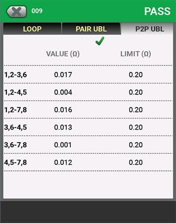
Figure 4. Versiv display of pair-to-pair resistance unbalance results.
3. Installation and Troubleshooting
Knowing the capacity of the PSE and the requirements of the PD make installation and troubleshooting much simpler. Unfortunately, in the real world, technicians supporting PoE powered devices may not have access to that information. They can easily check the requirements of a EA Certified PD, but in most cases, the tech working quite a distance from the PSE, so they’re faced with a long walk back to the telecommunications closet or data center to find out the capabilities of the switch. Then they’re faced with figuring out which cable goes to their PD. In many instances, they might not have access to the PSE and would need to contact the IT team to find out. A tech could waste half a day tracking the cable and accessing the switch.
Fluke Networks has developed two tools to solve these problems and save the tech hours of frustration: The LinkIQ™ Cable+Network Tester and the MicroScanner™ PoE. Simply plug either tool into the cable, and if it’s connected to a PSE, it will display the class (0-8) of power available on the link. The tech can then compare that to the requirements of the PD and know if sufficient power will be available. The LinkIQ performs a further test by placing a load on the PSE to determine if the switch and cabling link are capable of delivering the advertised power. The MicroScanner™ PoE has successfully completed the Ethernet Alliance Gen2 PoE Certified program test plan, providing confidence that it will work properly with all IEEE-compliant devices. The tester is also designed to work with a wide variety of non-IEEE-compliant technologies, but since there’s no certification program for that, you’ll just have to take our word for it.
These testers are invaluable to the tech in many other ways. They will identify the speed of the port up to 10 Gbps. A slow port may limit the performance of an access point or camera. If the cable has been damaged, they displays the length of each pair, potential breaks or other failures. Cables can also be unplugged or misrouted – so these testers can act as a tone source for tracing the cable. Identifiers can be connected to remote cables to determine where they go. The LinkIQ offers additional features: characterizing the performance of the cabling up to 10 Gb/s, displaying the name, port and VLAN number of a connected switch. Finally, the LinkIQ can generate reports for the cabling or the switch and store or print them using the popular LinkWare™ PC software.
Pick the right equipment, certify the cable’s capable and then make sure your tech can check and troubleshoot the installation and your PoE project will go smoothly.
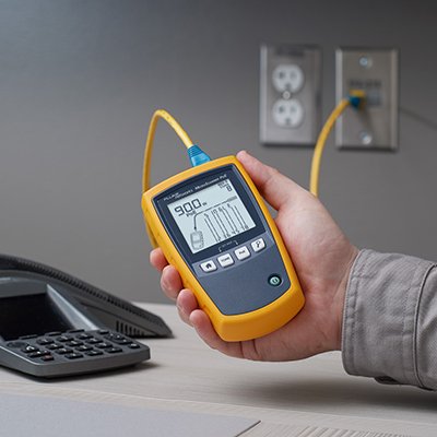
Figure 5. The MicroScanner PoE is Ethernet Alliance Gen2 PoE certified and can detect the power offered by the PSE plus the network’s speed, and features a suite of cable testing features.
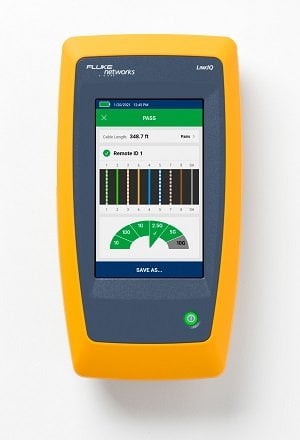
Figure 6.: The LinkIQ Cable+Network tester characterizes cable performance, displays switch port information and detects and loads PoE for thorough measurements.
|
|
|||
|
Cable Troubleshooting |
X |
X |
X |
|
Cable Performance Tests |
|
10 Mb/s to 10 Gb/s |
Certification to TIA, ISO and International Standards |
|
Resistance Measurements for PoE |
|
|
X |
|
Switch Port Speed Identification |
X |
X |
|
|
Switch Tests (Name, Port, VLAN) |
|
X |
|
|
PoE Port Testing |
X |
X |
|
|
Loaded PoE Port Test |
|
X |
|
|
Reporting |
|
Figure 7. Comparison of Fluke Networks tests for PoE devices and cabling.