OptiFiber® Pro Series OTDRs
Download PDF
Overview
The OptiFiber Pro® Series OTDRs are the Tier 2 (extended) fiber certification solution for Datacenters, Outside Plant (OSP), FTTx and PON environments and are part of the Versiv™ Cabling Certification system. The system includes copper certification and OLTSmodules. Versiv is designed around the revolutionary ProjX™ management system and Taptive™ user interface. ProjX tracks jobs to ensure they're done correctly the first time, thus reducing rework. With the intuitive Taptive user interface, instrument set-up and operation are so simple, even operators with limited cabling skills can successfully test and troubleshoot a system. Analysis of measurement data and professional test reports are easy with the familiar LinkWare™ management software.
On This Page
- Troubleshoot and Document Fiber Faster
- Unique Certification with Flexibility and Efficiency
- Taptive User Interface
- At Home in the Datacenter
- SmartLoop OTDR
- High Dynamic Range (HDR) Modules for Outside Plant Applications
- Splitter detection
- Macrobend detection
- Expert Manual Mode
- Edit events
- Span a portion of a link
- Rugged Metal LC Connectors
- LinkWare Live
- LinkWare™ Management Software
- Stackable results & batch process of traces via LinkWare PC
- Gold Support
- OptiFiber Pro Specifications
- OptiFiber Pro HDR Specifications
- OptiFiber Pro Series Specifications
- Technical Specifications
- Accessories
Troubleshoot and Document Fiber Faster
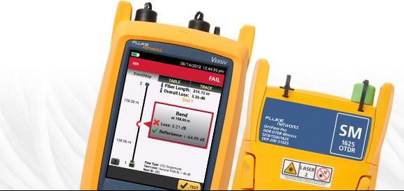
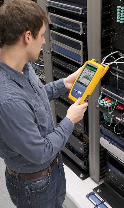
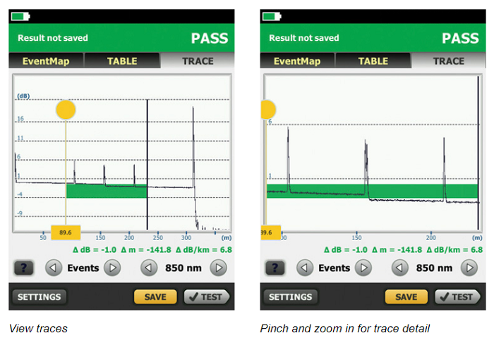
Fluke Networks' OptiFiber Pro Series OTDRs are designed to make every level of user more efficient whether working in data centers, outside plant, FTTx or PON applications. Novice users can set up and shoot traces in no time by using the Auto OTDR function which analyzes the fiber under test and then chooses appropriate settings. The EventMap™ feature analyzes traces like an expert, calculating overall loss and reflectance, indicating events such as splices, splitters bends and connectors. Experts can use these settings as the starting point for the Expert Manual Mode to experiment with the trace and uncover details of interest. OptiFiber Pro features an advanced touchscreen interface with pinch and zoom for analysis that's not only deep, but simple to master.
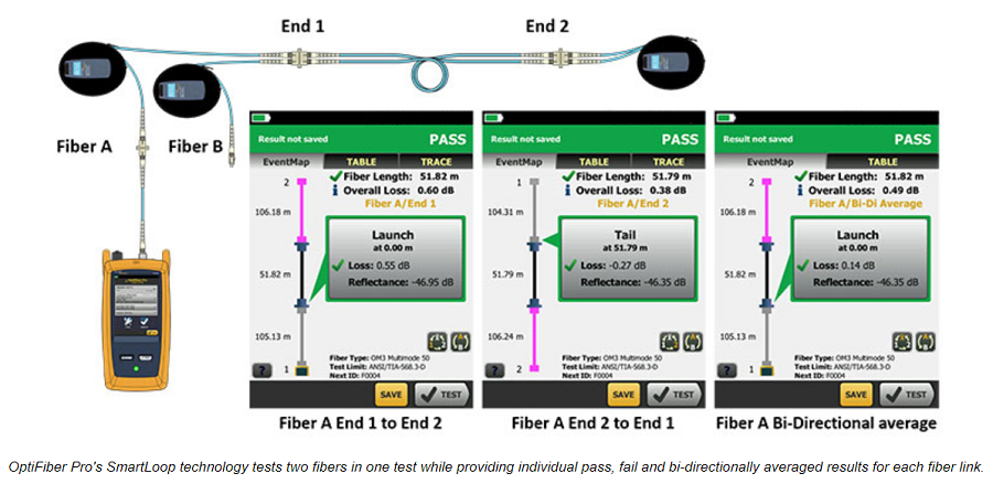
OptiFiber Pro's patented SmartLoop™ capability enables automated testing and analysis of two fibers in a single test in compliance with standards requirements. Not only does this cut the testing time by at least half, but it also allows the tech to immediately see bi-directional averaged test results without moving the OTDR to the far end or using external software.
As a member of the of the Versiv family, OptiFiber Pro offers a single user interface to cover a wide variety of fiber types and wavelengths: 850, 1300, 1310, 1490, 1550 and 1625 nm along with optional modules for copper and Tier 1 (optical loss) certification and fiber inspection. A single report for an entire job can quickly be generated for all supported media types using the industry standard LinkWare software.
Unique features:
- Taptive user interface puts advanced data analysis, easy set-up and operation at the fingertips of of technicians of all skill levels.
- SmartLoop OTDR enables automated testing and analysis of two fibers in a single test, eliminating the need to travel to the far end of the connection to perform tests.
- Multiple wavelengths support a variety of applications: 850, 1300, 1310, 1490, 1550, 1625 nm.
- Splitter detection for automated discovery of splitters. Up to 3 cascaded splitters may be found or manually configured.
- Macrobend detection for automatic identification of bends.
- Expert Manual Mode – simplifies experimentation which allows you to zero in on the part of the trace that interests you.
- Ability to edit or add events – Add 0 dB events, such as perfect splices, not seen by the OTDR or change an event to the correct type: APC connector, a splice or loss event.
- Span a portion of a link – allows you to select a segment of fiber for analysis within a longer segment. Span allows you to test only the portion for which you are responsible.
- Stackable results and batch processing of traces. When testing many identical fibers at a time, batch processing allows users to look at multiple traces and stack them to spot differences and/or batch edit events quickly.
- Compatible with LinkWare™ Live. LinkWare Live enables you to easily track job progress, get real-time access to test results to quickly fix problems in the field, and easily transfer and consolidate test results from the tester to LinkWare™ PC Cable Test Management Software.
Performance:
- Test times as short as two seconds in Quick Test mode.
- Quickly test datacenter fiber with pre-programmed settings.
- Auto OTDR modes analyze fiber runs to set key parameters: Range, Pulse Width, and Averaging Time, enabling any user to test like an expert. Expert Manual Mode allows users to easily modify these parameters to zero in on important details.
- Troubleshoot datacenter fiber links with short patch cables and many connectors because of ultra short dead zones.
- Easily characterize all connectors, splices and areas of high loss with graphical EventMap view.
- Pass/Fail certification of fiber optic connector endfaces.
- Document-only reporting for OSP applications.
- ProjX management system increases return on investment by reducing errors.
- Reduce network downtime by quickly and precisely identifying faults on all fiber types.
- Built-in Visual Fault Locator (VFL) easily identifies damaged fibers.
Standards:
- Full OTDR capability that certifies fiber performance based on industry standards or customer specifications
- Complaint with ISO and TIA standards
Unique Certification with Flexibility and Efficiency
An important aspect in maximizing an OTDR’s value is to properly plan its day-to-day usage. With the ProjX management system, OptiFiber Pro allows a project manager to define each user’s role, settings and the associated tasks to be performed – transforming the OTDR into an all-in-one fiber testing tool complete with planning, inspection, certification and reporting.
Advantages:
- Powerful ProjX management system facilitates OTDR sharing with clear job assignment for each operator
- Easy monitoring of job progress with pass/fail or document only results
- Built-in Visual Fault Locator (VFL) to facilitate troubleshooting
- On-screen report generation and upload to LinkWare™ application
- Integrated Wi-Fi allows you to easily upload results to LinkWare™ Live
Taptive User Interface
Most OTDRs are designed for a myriad of applications, causing the user interface to be difficult to navigate and interpret. OptiFiber Pro has the Taptive user interface which combines the latest “gesture-based” interface technology with a capacitive touchscreen to deliver the most innovative and user-friendly OTDR.
At Home in the Datacenter
Driven by server virtualization and multi-gigabit links between servers, networks and storage, the datacenter architecture employs more patch cords and dense topology connectors, rendering carrier-class OTDRs with long dead-zones ineffective. OptiFiber Pro not only makes fiber deployment in datacenters possible, but provides the highest level of accuracy for quick problem resolution.
Advantages:
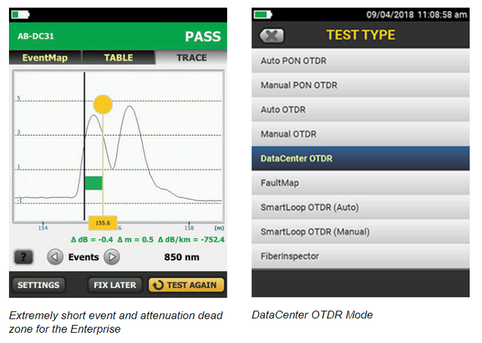
- Ultra-short event and attenuation dead-zones allows precise location of events and faults on fiber links
- Datacenter OTDR™ mode automatically sets the configuration to quickly test datacenter fiber
- The EventMap feature depicts fiber events in a way that requires no trace analysis expertise
Extremely short event and attenuation dead zone for the Enterprise
OptiFiber Pro leverages the most sophisticated optical technology to provide the shortest event dead zone (0.5 m typical for MM) and attenuation dead zone (2.5 m typical for MM and 3.6 m typical for SM) of any OTDR. This technological advancement allows OptiFiber Pro to detect and measure closely spaced faults where no other OTDR can in today’s connector-rich datacenter and storage area network environments.
Two second trace per wavelength
Another breakthrough with OptiFiber Pro is the data acquisition speed. While in Quick Test mode, a complete set of data are acquired in as little as two seconds per wavelength. OptiFiber Pro then analyzes the data and displays it as an EventMap event, Table or Trace. The end result is less time spent testing and more time performing other tasks.
DataCenter OTDR™ Mode
With a simple one-touch selection, users enter DataCenter OTDR mode – without setup time for fine tuning as needed in legacy OTDRs. DataCenter OTDR mode automatically detects OTDR parameters – end-detection algorithms, pulse widths – without getting confused by the short links or number of connectors.
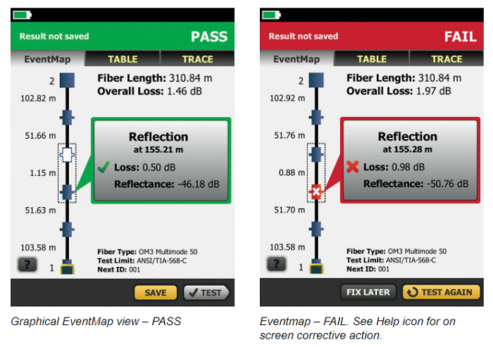
Graphical EventMap view
To eliminate the learning curve associated with reading an OTDR trace, OptiFiber Pro’s advanced logic automatically interprets the information to create a detailed and graphical map of events that includes connectors, splices and anomalies. To accommodate different preferences, users can easily switch between the EventMap, the Event Table and the Trace for test details. Any faulty events will be highlighted with RED icons to facilitate quick troubleshooting.
On-screen “help” suggests corrective action(s) for resolving fiber problems during each testing step. The “help” offered is context sensitive which allows users to quickly pinpoint possible resolutions. An easy-to-read, gray icon in the bottom, left-hand corner shows detailed corrective action recommendations.
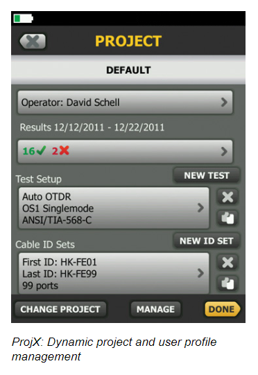
Dynamic project and user profile management with ProjX management system
OptiFiber Pro enhances job efficiency by allowing the project manager to create and manage operator and job profiles per project. Defined jobs or sets of cable IDs can be assigned to specific operators. The progress and status of each project can also be easily monitored.
SmartLoop OTDR
The award-winning SmartLoop OTDR enables automated testing and analysis of two fibers in a single test while meeting standards requirements. This patented process automatically separates the two fibers for individual pass/fail analysis, display, and reporting. Not only does this cut the testing time by at least half, it also enables instant bi-directional averaged test results without moving the OTDR to the far end. In addition to getting the job done quicker, SmartLoop meets the standards requirements of leaving the launch and tail fibers in their initial locations during both bi-directional tests. SmartLoop OTDR further enhances the ease and speed of testing in environments where the far end is difficult of even dangerous to reach because the OTDR never has to be moved to the far end.
Test it right and test it fast with SmartLoop – included for free in all OptiFiber Pro modules.
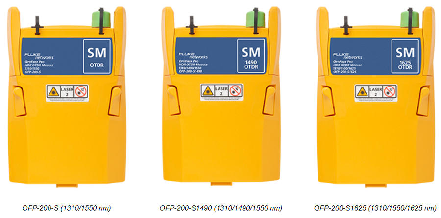
High Dynamic Range (HDR) Modules for Outside Plant Applications
OptiFiber Pro HDR has a dynamic range up to 42 dB and adds new wavelengths for outside plant/FTTx/PON testing requirements. Three wavelength combinations are available depending upon your requirements:
- 1310 / 1550 nm
- 1310 / 1490 / 1550 nm
- 1310 / 1550 / 1625 nm
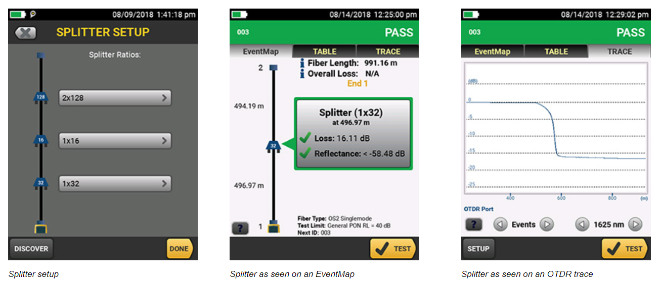
Splitter detection
OptiFiber Pro HDR is optimized for FTTx/PON testing through splitters. 1x16 and 1x32 are most commonly found today but OptiFiber Pro HDR is future proofed for testing even nx128 splitters. With its Discover function, you can automatically locate splitters and their ratios. Up to 3 cascaded splitters can be configured in the setup.
OptiFiber Pro HDR provides two PON test suites: Auto PON OTDR and Manual PON OTDR:
- Auto PON OTDR – The tester automatically selects settings that give you the best view of the events on OSP (outside plant) cabling. The tester automatically uses the DISCOVER function to identify splitters. This mode is the easiest to use and is the best choice for most applications.
- Manual PON OTDR – This mode lets you select settings to control the parameters of the trace. You can also enter the ratios of splitters that you know are on the link or use the DISCOVER function to locate splitters and identify their ratios.
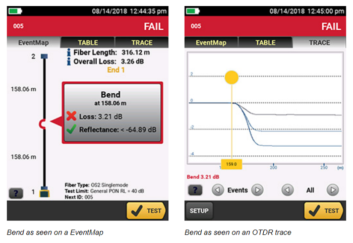
Macrobend detection
A bend in a fiber cable, if pulled around a sharp corner for instance, allows light to escape from the fiber’s core. The resulting macrobend may be a risk for mechanical or optical failure. OptiFiber Pro automatically identifies bends and their location by comparing the loss of an event at multiple wavelengths.
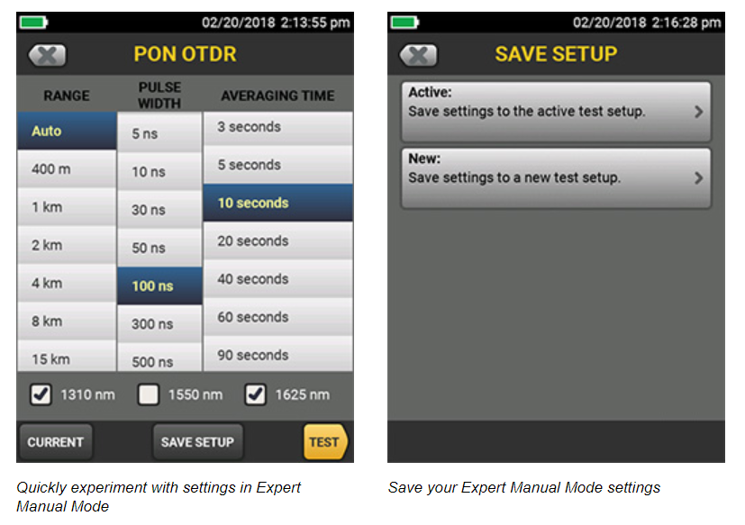
Expert Manual Mode
Starting with settings from Auto OTDR mode, Expert Manual Mode allows the user to quickly experiment with settings to uncover details of interest:
- Easy to use manual settings – simplifies experimentation via on the trace screen
- Change the range, pulse width, averaging time, and wavelength
- Try the setting out before saving
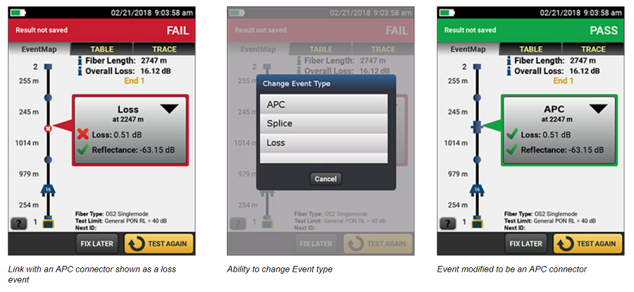
Edit events
When testing or certifying fiber runs, you want the test results to reflect the links as-built. Sometimes an OTDR can misidentify or not find all the actual events within a link. The Edit Event function provides users with the ability to edit, add or remove events including:
- Changing an event to: an APC connector, a splice or a loss event
- Allows the insertion of a splice, as a 0dB event, at a given location when the splice is hidden due to noise or the splice loss is lower than the minimum detection threshold
- Once the event is modified, the PASS/FAIL status of the link will be updated to reflect the modification
- APC connectors may be identified as a splice instead of as an APC connector because they are non-reflective like a splice. This can cause problems since the loss budget for a splice is less than that of an APC connector. Allowing you to edit the splice and change it to an APC connector allows the loss budget to be calculated correctly for the link.
- Edited events are marked in reports so they can easily be identified as having been edited
Span a portion of a link
When testing a fiber run (particularly in outside plant applications) you may only be interested in a small section of the cabling. For example, if you are repairing a short section of a longer trunk, span allows you to define the start and end of your short section so that the OTDR analyzes only the section that you repaired.
- Provides the ability to perform PASS/FAIL analysis on a section of fiber under test
- PASS/FAIL analysis is only generated for events located with the span distance
- Events outside the span range are evaluated as info only
Fiber Endface Inspection and Certification
OptiFiber Pro incorporates the FiberInspector Pro video inspection system which enables you to quickly inspect and certify fiber end-faces inside ports or patch cords. Its 1-second automated PASS/FAIL grading eliminates human subjectivity and enables anyone to become a fiber inspection expert. Results can be saved in the certification report along side OptiFiber Pro's OTDR results.
Rugged Metal LC Connectors
Fluke Networks Test Reference Cords and Launch Fibers with LC connectors feature our unique metal latch design. Traditional LC connectors use a single-piece plastic design that flexes the latching mechanism each time the connector is inserted and removed and eventually breaks, making them unsuitable for repeated use in testing. The Fluke Networks Metal LC latching system uses a multi-piece metal design with a spring located between the latch and connector body. Since this latch is not part of the body and does not flex, the life of the latching mechanism is greatly improved, thereby extending the life of the LC connector and therefore the TRC’s and launch cords.
The Metal LC connector is compliant with IEC 61754-20 and TIA-604-10B intermateability standards. That latch has also been tested for up to 10,000 insertions with no degradation in performance and passes all Telecordia GR-326-CORE durability tests including thermal, humidity, vibration, flex, impact, and salt spray. While the connector itself is the most rugged available, the glass fiber endface is still susceptible to damage, so it’s important to inspect the endface to make sure it’s contaminant-free and to properly clean it if necessary.
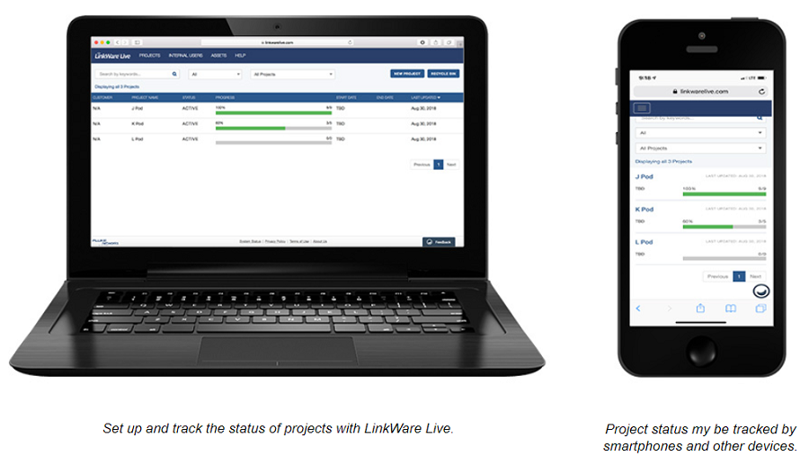
LinkWare Live
LinkWare Live is a Software as a Service from Fluke Networks for cabling professionals managing multiple projects that quickly, easily and affordably provides unmatched job visibility and superior project control from anywhere at anytime.
LinkWare Live provides an easy to read dashboard that shows an overview of the project status and a project activity to ensure projects are completed on time. It removes the hurdles in data management by giving the ability to directly upload and consolidate test results from multiple testers. You can quickly validate projects and test results in real-time with browser based ease to avoid any future rework due to incorrect testing or missing test results. Use any smart device with a browser to validate and check projects or test results. LinkWare™ Cable Test Management Software also connects to the LinkWare Live service enabling you to download test results into the LinkWare PC Cable Test Management Software to generate professional reports in a common format.
The OptiFiber Pro OTDR connects to the LinkWare Live Service to directly upload results from the tester which provide access to test-results in real-time from anywhere.
LinkWare™ Management Software
With LinkWare management software, OptiFiber Pro users can easily access the ProjX management system data, generate reports and upgrade the software in their testers. Project managers have full capabilities to monitor workflow and consolidate test results. LinkWare Stats provides automated statistical reports. This application moves you above and beyond the page-per-link report to see your entire cabling infrastructure in one summary. It analyzes and transforms LinkWare test results into charts to reveal your cabling plant performance. The report even summarizes your entire cabling infrastructure in a compact, graphical format so it's easy to verify margins and spot anomalies. Previous versions of LinkWare are backwards compatible with new versions, so you can stay current and integrate tests from different testers into one-test report.
Combine OLTS Tier 1 (basic) and OTDR Tier 2 (extended) fiber certification results in a single report while allowing management of multiple jobs simultaneously. Users can provide the finishing touch by adding their company logo to the report and before offering to their customers for system acceptance. Keep your business tools simple. No matter which Fluke Networks cabling certification tester you use, LinkWare reports it all.
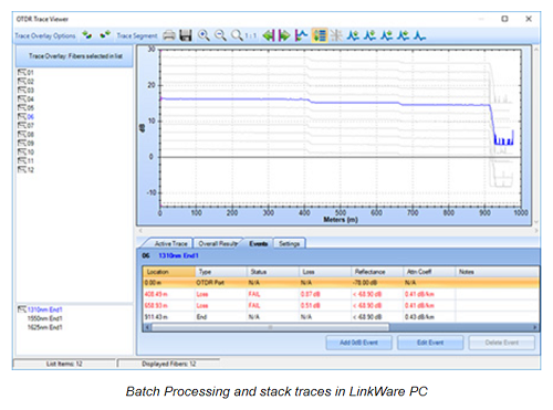
Stackable results & batch process of traces via LinkWare PC
LinkWare PC allows for the batch processing of traces so you can quickly and easily make edits to many traces at one time. Stacking traces allows you to visually identify differences between identical fibers, such as strands within a trunk. LinkWare PC does this by allowing multiple traces to be overlaid and stacked with separation so that differences in the graph can easily be spotted.
Gold Support
You’ve made an investment in the best equipment in the industry. Protect your investment and limit unplanned downtime and costs with the best custom-built maintenance program.
Membership in Fluke Networks’ Gold program provides expanded product coverage and support to ensure you get the most out of your investment.
| Benefits of Gold Include: |
1 year GOLD MEMBERSHIP |
Standard Warranty on New Products |
After Standard Warranty Ends |
|---|---|---|---|
|
90 Day Limited Repair or Replacement on Manufacturing Defects (Accessories) |
✓ | ✓ | |
| FREE Repairs | ✓ |
Only on Mainframe and Module Mfg. Defects |
|
| FREE Annual Calibration | ✓ | ||
| FREE 2-Way Shipping | ✓ | ||
|
Zero Downtime During Repair/Calibration with FREE Loaner** |
✓ | ||
| FREE Accessory Replacements* | ✓ | ||
| <2 Hour Technical Support Response Time | ✓ | < 24 Hours | < 24 Hours |
| 24x7x365 Customer Support – Phone and Email | ✓ | 5:00AM to 5:00PM (PST) | 5:00AM to 5:00PM (PST) |
|
Technical Support Engineer as Primary Case Handler |
✓ | ||
| Exclusive Promotions | ✓ |
*Applies to accessories included in the original product bundle
**Available in certain geographies (please schedule 4-6 weeks in advance)
| OptiFiber Pro Series OTDRs | ||
|---|---|---|
| OptiFiber Pro | OptiFiber Pro HDR | |
| Models in Series |
OFP2-100-M (850, 1300 nm) OFP2-100-S (1310, 1550 nm) OFP2-100-Q (850, 1300, 1310, 1550 nm) |
OFP2-200-S (1310, 1550 nm) OFP2-200-S1490 (1310, 1490, 1550 nm) OFP2-200-S1625 (1310, 1550, 1625 nm) |
| Application | Enterprise, Datacenter, Campus | FTTx, Outside Plant, PON, POLAN, Access |
| Wavelengths |
850 nm 1300 nm 1310 nm 1550 nm |
1310 nm 1490 nm 1550 nm 1625 nm |
| Compatible fiber types |
50/125 µm, 62.5 µm, Singlemode |
Singlemode |
| OTDR Port Connector | Cleanable UPC ferrule with removable SC adapter | Cleanable APC ferrule with removable SC adapter |
| Supplied Test Cords | Launch Fibers for testing LC systems | 2m TRC for testing SCAPC systems |
| OTDR types | Auto, Datacenter, Manual | Auto, Auto PON, Manual, Manual PON |
| Event Dead Zone |
850 nm: 0.5 m (typical), 1300 nm: 0.7 m (typical), 1310 nm: 0.6 m (typical), 1550 nm: 0.6 m (typical) |
1310 nm: 0.7 m (typical), 1490 nm: 0.7 m (typical), 1550 nm: 0.7 m (typical), 1625 nm: 0.7 m (typical) |
| Attenuation Dead Zone |
850 nm: 2.5 m (typical), 1300 nm: 4.5 m (typical), 1310 nm: 3.6 m (typical), 1550 nm: 3.7 m (typical) |
1310 nm: 4 m (typical), 1490 nm: 4 m (typical), 1550 nm: 4 m (typical), 1625 nm: 4 m (typical) |
| PON Dead Zone | N/A | 30 m (typical) |
| Dynamic Range |
850 nm: 28 dB (typical) 1300 nm: 30 dB (typical) 1310 nm: 32 dB (typical) 1550 nm: 30 dB (typical) |
1310 nm: 42 dB (typical) 1490 nm: 41 dB (typical) 1550 nm: 41 dB (typical) 1625 nm: 40 dB (typical) |
| Reflectance range |
850 nm: -14 dB to -57 dB (typical), 1300 nm: -14 dB to -62 dB (typical), 1310 nm: -14 dB to -65 dB (typical), 1550 nm: -14 dB to -65 dB (typical) |
1310 nm: -14 to -70 dB (typical), 1490 nm: -14 dB to 70 dB (typical), 1550 nm: -14 dB to -70 dB (typical), 1625 nm: -14 dB to -70 dB (typical) |
| Sampling Resolution | 3 cm to 400 cm | 3 cm to 2 m |
| Sampling Points | Up to 64,000 | Up to 129,000 |
| Expert Manual Mode | Yes | Yes |
| SmartLoop with on-board Bi-directional averaging | Yes | Yes |
| Macrobend detection | Yes | Yes |
| Span Support | Coming early 2019 | |
| Event editing and additions | Coming early 2019 | |
| VFL | Yes | Yes |
OptiFiber Pro Specifications
|
Multimode Module (OFP2-100-M) |
Singlemode Module (OFP2-100-S) |
Quad Module (OFP2-100-Q) |
|
|---|---|---|---|
| Wavelengths |
850 nm +/- 10 nm 1300 nm +35/-15 nm |
1310 nm +/- 25 nm 1550 nm +/- 30 nm |
850 nm +/- 10 nm, 1300 nm +35/-15 nm, 1310 nm +/- 25 nm, 1550 nm +/- 30 nm |
| Compatible fiber types |
50/125 µm 62.5/125 µm |
Singlemode | 50/125 μm, 62.5/125 μm, Singlemode |
| Event dead zone 1 |
850 nm: 0.5 m (typical) 1300 nm: 0.7 m (typical) |
1310 nm: 0.6 m (typical) 1550 nm: 0.6 m (typical) |
850 nm: 0.5 m (typical), 1300 nm: 0.7 m (typical), 1310 nm: 0.6 m (typical), 1550 nm: 0.6 m (typical) |
| Attenuation dead zone 2 |
850 nm: 2.5 m (typical) 1300 nm: 4.5 m (typical) |
1310 nm: 3.6 m (typical) 1550 nm: 3.7 m (typical) |
850 nm: 2.5 m (typical), 1300 nm: 4.5 m (typical), 1310 nm: 3.6 m (typical), 1550 nm: 3.7 m (typical) |
| Dynamic range 3, 5, 6 |
850 nm: 28 dB (typical) 1300 nm: 30 dB (typical) |
1310 nm: 32 dB (typical) 1550 nm: 30 dB (typical) |
850 nm: 28 dB (typical), 1300 nm: 30 dB (typical), 1310 nm: 32 dB (typical), 1550 nm: 30 dB (typical) |
| Max distance range setting | 40 km | 130 km | MM: 40 km, SM: 130 km |
|
Distance measurement range 4, 5, 7, 8, 9, 10 |
850 nm: 9 km 1300 nm: 35 km |
1310 nm: 80 km 1550 nm: 130 km |
850 nm: 9 km, 1300 nm: 35 km, 1310 nm: 80 km, 1550 nm: 130 km |
| Reflectance range 4, 5 |
850 nm: -14 dB to -57 dB (typical) 1300 nm: -14 dB to -62 dB (typical) |
1310 nm: -14 dB to -65 dB (typical) 1550 nm: -14 dB to -65 dB (typical) |
850 nm: -14 dB to -57 dB (typical), 1300 nm: -14 dB to -62 dB (typical), 1310 nm: -14 dB to -65 dB (typical), 1550 nm: -14 dB to -65 dB (typical) |
| Sample resolution | 3 cm to 400 cm | 3 cm to 400 cm | 3 cm to 400 cm |
| Pulse widths (nominal) |
850 nm: 3, 5, 20, 40, 200 ns 1300 nm: 3, 5, 20, 40, 200, 1000 ns |
3, 10, 30, 100, 300, 1000, 3000, 10000, 20000 ns |
850 nm: 3, 5, 20, 40, 200 ns, 1300 nm: 3, 5, 20, 40, 200, 1000 ns, 1310/1550 nm: 3, 10, 30, 100, 300, 1000, 3000, 10000, 20000 ns |
| Test time (per wavelength) | Auto setting: 5 sec (typical) | Auto setting: 10 sec (typical) |
Auto setting: MM - 5 sec (typical) SM – 10 sec (typical) |
| Quick test setting: 2 sec (typical) | Quick test setting: 5 sec (typical) |
Quick test setting: MM – 2 sec (typical) SM – 5 sec (typical) |
|
| Best resolution setting: 2 to 180 sec | Best resolution setting: 5 to 180 sec |
Best resolution setting: MM – 2 to 180 sec SM – 5 to 180 sec |
|
|
FaultMap setting: 2 sec (typical), 180 sec (max) |
FaultMap setting: 10 sec (typical), 180 sec (max) |
FaultMap setting: MM – 2 sec (typical) MM – 180 sec (max) SM – 10 sec (typical) SM – 180 sec (max) |
|
|
DataCenter OTDR setting: 1 sec (typical at 850 nm), 7 sec (max) |
DataCenter OTDR setting: 20 sec (typical), 40 sec (max) |
DataCenter OTDR setting: MM – 1 sec (typical at 850 nm) MM – 7 sec (max) SM – 20 sec (typical) SM – 40 sec (max) |
|
|
Manual setting: 3, 5, 10, 20, 40, 60, 90, 120, 180 sec |
Manual setting: 3, 5, 10, 20, 40, 60, 90, 120, 180 sec |
Manual setting: MM - 3, 5, 10, 20, 40, 60, 90, 120, 180 sec SM - 3, 5, 10, 20, 40, 60, 90, 120, 180 sec |
|
|
1. Measured at 1.5 dB below non-saturating reflection peak with the shortest pulse width. Reflection peak ‹ -40 dB for multimode and ‹ - 50 dB for singlemode. 2. Measured at +/- 0.5 dB deviation from backscatter with the shortest pulse width. Reflection peak ‹ -40 dB for multimode and ‹ - 50 dB for singlemode. 3. For typical backscatter coefficient for OM1 fiber: 850: -65 dB, 1300: -72 dB. 4. Typical backscatter and attenuation coefficients for OM2-OM4 fiber: 850 nm: -68 dB; 2.3 dB/km: 1300 nm: -76 dB; 0.6 dB/km. 5. Typical backscatter and attenuation coefficients for OS1-OS2 fiber: 1310nm : -79 dB; 0.32 dB/km; 1550 nm: -82 dB; 0.19 dB/km. 6. SNR=1 method, 3 minute averaging, widest pulse width. 7. 850 = 9 km typical to find the end or 7 km typical to find a 0.1 dB event (with a maximum of 18 dB attenuation prior to the event). 8. 1300 = 35 km typical to find the end or 30 km typical to find a 0.1 dB event (with a maximum of 18 dB attenuation prior to the event). 9. 1310 = 80 km typical to find the end or 60km typical to find a 0.1 dB event (with a maximum of 20 dB attenuation prior to the event). 10. 1550 = 130 km typical to find the end or 90 km typical to find a 0.1 dB event (with a maximum of 18 dB attenuation prior to the event). |
|||
OptiFiber Pro HDR Specifications
|
Singlemode module (OFP2-200-S) |
Singlemode + 1490 nm module (OFP2-200-S1490) |
Singlemode + 1625 nm module (OFP2-200-S1625) |
|
|---|---|---|---|
| Wavelengths |
1310 nm +/- 25 nm 1550 nm +/- 20 nm |
1310 nm +/- 25 nm 1490 nm +/- 20 nm 1550 nm +/- 20 nm |
1310 nm +/- 25 nm 1550 nm +/- 20 nm 1625 nm +/- 20 nm |
| Compatible fiber types | Singlemode | ||
| OTDR Port Connector | Cleanable APC ferrule with removable SC adapter | ||
| Event dead zone1 | 0.7 m (typical) | ||
| Attenuation dead zone2 | 4 m (typical) | ||
| PON dead zone3 | 30 m (typical) | ||
| Dynamic range 4, 5 |
1310 nm: 42 dB (typical) 1550 nm: 41 dB (typical) |
1310 nm: 42 dB (typical) 1490 nm: 41 dB (typical) 1550 nm: 41 dB (typical) |
1310 nm: 42 dB (typical) 1550 nm: 41 dB (typical) 1625 nm: 40 dB (typical) |
| Reflectance range 4 | -14 to -70 dB (typical) | ||
| Sampling resolution | 3 cm to 2 m | ||
| Sampling points | Up to 129000 | ||
| Pulse widths (nominal) | 5, 10, 30, 50, 100, 300, 500, 1000, 3000, 5000, 10000, 20000 ns | ||
| Distance uncertainty | +/-(1 + 0.0005*distance + 0.5*resolution) | ||
| Linearity | ± 0.03 dB/dB | ||
| Reflectance uncertainty | ± 2 dB | ||
| Test Time (per wavelength) | Auto setting: 5 seconds/wavelength (typical) | ||
| Auto PON setting: 10 seconds/wavelength (typical) | |||
| Manual setting: 3, 5, 10, 20, 40, 60, 90, 120, 180 seconds/wavelength | |||
| Manual PON setting: 3, 5, 10, 20, 40, 60, 90, 120, 180 seconds/wavelength | |||
| Quick test setting: 3 seconds/wavelength (typical) | |||
| Best resolution setting: 5 to 180 seconds/wavelength | |||
| Laser Classification | Class 1 CDRH Complies to EN 60825-2, 3rd Edition | ||
| Calibration Period | 1 year | ||
|
1. Measured at 1.5 dB below non-saturating reflection peak with the shortest pulse width. Reflection peak at - 50 dB. 2. Measured at +/- 0.5 dB deviation from backscatter with the shortest pulse width. Reflection peak‹ - 50 dB. 3. Measured at +/- 0.5 dB deviation from backscatter after 1:16 non-reflective splitter using 50 ns pulse width and 3 cm sampling resolution. 4. Typical backscatter coefficients for OS1-OS2 fiber: 1310 nm: -79 dB; 1490 nm: -81 dB; 1550 nm: -82 dB; 1625 nm: -84 dB. 5. 3 minute averaging, widest pulse width, 100 km fiber length, SNR = 1. |
|||
OptiFiber Pro Series Specifications
| FiberInspector probe specifications | |
|---|---|
| Magnification | ~ 200X with OptiFiber Pro Display |
| Light source | Blue LED |
| Power source | Versiv Mainframe |
| Field of View (FOV) | Horizontal: 425 µm, Vertical: 320 μm |
| Minimum detectable particle size | 0.5 µm |
| Dimensions | Approximately 6.75 in x 1.5 in (1175 mm x 35 mm) without adapter tip |
| Weight | 200 g |
| Temperature range | Operating: 32°F to 122°F (0 °C to +50 °C), Storage: -4°F to +158°F (-20°C to +70°C) |
| VFL specifications | |
|---|---|
| On/Off control | Mechanical switch and a button on the touch screen |
| Output power | 316 µW (-5 dBm) ≤ peak power ≤ 1.0 mW (0 dBm) |
| Operating wavelength | 650 nm nominal |
| Spectral width (RMS) | ±3 nm |
| Output modes | Continuous wave Pulsed mode (2 Hz to 3 Hz blink frequency) |
| Connector adapter | 2.5 mm universal |
| Laser safety (classification) | Class II CDRH Complies to EN 60825-2 |
| For complete kit configurations, please visit www.flukenetworks.com/versivconfig | |
Technical Specifications
| General specifications | |
|---|---|
| Weight | Mainframe with module and battery: 3 lbs, 5 oz (1.28 kg) |
| Dimensions | Mainframe with module and battery: 2.625 in x 5.25 in x 11.0 in ( 6.67 cm x 13.33 cm x 27.94 cm) |
| Battery | Lithium ion battery pack, 7.2 volts |
| Battery life | 8 hr Auto OTDR operation, dual wavelength no video probe connected, 150 m of fiber |
| Integrated Wi-Fi | Meets IEEE 802.11 a/b/g/n; dual band (2.4 GHz and 5 GHz) |
| Charge Time | |
|---|---|
| Tester off | 4 hours to charge from 10% to 90% capacity |
| Tester on | 6 hours to charge from 10% to 90% capacity with the tester on |
| Environmental specifications | |
|---|---|
| Operating temperature* | -18º C to 45º C |
| Non-operating temperature | -30º C to 60º C |
| Operating altitude | 4,000 m (13,123 ft), 3,200 m (10,500 ft) with AC adapter |
| Storage altitude | 12,000 m |
| EMC | EN 61326-1 |
|
• Using battery power. With AC power: 0º C to 45º C. Real Time Trace function used for no more than 5 minutes in a 15-minute period. Maximum ambient temperature is 35º C for continuous use of the Real Time Trace function. • Do not keep battery at temperatures below -20° C (-4° F) or above 50° C (122° F) for periods longer than one week to maintain battery capacity. |
|
Accessories
| OptiFiber Pro Wireless models | |
|---|---|
| Model | Description |
| OFP2-100-QI | OptiFiber Pro Quad OTDR V2 with inspection kit and Wi-Fi |
| OFP2-100-QI/GLD | OptiFiber Pro Quad OTDR V2 with inspection kit, Wi-Fi and 1 YR Gold Support |
| OFP2-CFP-QI | OptiFiber Pro, CertiFiber Pro Quad V2 with inspection and Wi-Fi |
| OFP2-100-Q | OptiFiber Pro Quad OTDR V2 kit with Wi-Fi |
| OFP2-100-Q/GLD | OptiFiber Pro Quad OTDR V2 kit with Wi-Fi and 1 YR Gold Support |
| OFP2-100-MI | OptiFiber Pro Multimode OTDR V2 with inspection kit and Wi-Fi |
| OFP2-100-M | OptiFiber Pro Multimode OTDR V2 with Wi-Fi |
| OFP2-100-SI | OptiFiber Pro Singlemode OTDR V2 with inspection kit and Wi-Fi |
| OFP2-100-S | OptiFiber Pro Singlemode OTDR V2 with Wi-Fi |
| OptiFiber Pro Non-wireless models | |
|---|---|
| Model | Description |
| OFP2-100-Q-NW | OptiFiber Pro Quad OTDR V2 kit |
| OFP2-100-M-NW | OptiFiber Pro Multimode OTDR V2 kit |
| OFP2-100-S-NW | OptiFiber Pro Singlemode OTDR V2 kit |
| OptiFiber Pro HDR Wireless models | |
|---|---|
| Model | Description |
| OFP2-200-S | OptiFiber Pro HDR OTDR V2 kit with Wi-Fi (1310, 1550 nm) |
| OFP2-200-S1490 | OptiFiber Pro HDR OTDR V2 kit with Wi-Fi (1310, 1490, 1550 nm) |
| OFP2-200-S1625 | OptiFiber Pro HDR OTDR V2 kit with Wi-Fi (1310, 1550, 1625 nm) |
| OFP2-200-Si | OptiFiber Pro HDR OTDR V2 with inspection kit with Wi-Fi (1310, 1550 nm) |
| OFP2-200-Si1490 | OptiFiber Pro HDR OTDR V2 with inspection kit with Wi-Fi (1310, 1490, 1550 nm) |
| OFP2-200-Si1625 | OptiFiber Pro HDR OTDR V2 with inspection kit with Wi-Fi (1310, 1550, 1625 nm) |
| OFP2-200-Si/GLD | OptiFiber Pro HDR OTDR V2 with inspection kit with Wi-Fi and 1 YR Gold Support (1310, 1550 nm) |
| OFP2-200-Si14/GLD | OptiFiber Pro HDR OTDR V2 with inspection kit with Wi-Fi and 1 YR Gold Support (1310, 1490, 1550 nm) |
| OFP2-200-Si16/GLD | OptiFiber Pro HDR OTDR V2 with inspection kit with Wi-Fi and 1 YR Gold Support (1310, 1550, 1625 nm) |
| OptiFiber Pro HDR Non-wireless models | |
|---|---|
| Model | Description |
| OFP2-200-S-NW | OptiFiber Pro HDR OTDR V2 kit (1310, 1550 nm) |
| OFP2-200-S1490-NW | OptiFiber Pro HDR OTDR V2 kit (1310, 1490, 1550 nm) |
| OFP2-200-S1625-NW | OptiFiber Pro HDR OTDR V2 kit (1310, 1550, 1625 nm) |
| UPC/UPC Launch Cords | |
|---|---|
| Model | Description |
| MMC-50-SCSC | Multimode 50 μm launch cord (105 m) for SC/SC |
| MMC-50-SCLC-M | Multimode 50 μm launch cord (105 m) for SC/LC - Metal |
| MMC-50-LCLC-M | Multimode 50 μm launch cord (105 m) for LC/LC - Metal |
| MMC-50-SCST | Multimode 50 μm launch cord (105 m) for SC/ST |
| MMC-50-STST | Multimode 50 μm launch cord (105 m) for ST/ST |
| MMC-50-SCFC | Multimode 50 μm launch cord (105 m) for SC/FC |
| MMC-50-FCFC | Multimode 50 μm launch cord (105 m) for FC/FC |
| MMC-50-SCE2K | Multimode 50 μm launch cord (105 m) for SC/E2K |
| MMC-62-SCSC | Multimode 62.5 μm launch cord (105 m) for SC/SC |
| MMC-62-SCLC-M | Multimode 62.5 μm launch cord (105 m) for SC/LC - Metal |
| MMC-62.5-LCLC-M | Multimode 62.5 μm launch cord (105 m) for LC/LC - Metal |
| MMC-62-SCST | Multimode 62.5 μm launch cord (105 m) for SC/ST |
| MMC-62.5-STST | Multimode 62.5 μm launch cord (105 m) for ST/ST |
| MMC-62-SCFC | Multimode 62.5 μm launch cord (105 m) for SC/FC |
| MMC-62.5-FCFC | Multimode 62.5 μm launch cord (105 m) for FC/FC |
| SMC-9-SCSC | Singlemode 9 μm launch cord (160 m) for SC/SC |
| SMC-9-SCLC-M | Singlemode 9 μm launch cord (160 m) for SC/LC - Metal |
| SMC-9-LCLC-M | Singlemode 9 μm launch cord (160 m) for LC/LC - Metal |
| SMC-9-SCST | Singlemode 9 μm launch cord (160 m) for SC/ST |
| SMC-9-STST | Singlemode 9 μm launch cord (160 m) for ST/ST |
| SMC-9-SCFC | Singlemode 9 μm launch cord (160 m) for SC/FC |
| SMC-9-FCFC | Singlemode 9 μm launch cord (160 m) for FC/FC |
| UPC/APC Launch Cords | |
|---|---|
| Model | Description |
| SMC-9-SCE2KAPC | Singlemode 9 μm launch cord (160 m) for SC/E2000 APC |
| SMC-9-SCSCAPC | Singlemode 9 μm launch cord (160 m) for SC/SCAPC |
| SMC-9-SCFCAPC | Singlemode 9 μm launch cord (160 m) for SC/FCAPC |
| SMC-9-SCLCAPC-M | Singlemode 9 μmlaunch cord (160 m) for SC/LCAPC - Metal |
| SMC-9-SCAPC/LC-M | Singlemode 9 μm launch cord (160 m) for SCAPC/LCUPC - Metal |
| SMC-9-SCAPC/FC | Singlemode 9 μm launch cord (160 m) for SCAPC/FCUPC |
| SMC-9-SCAPC/ST | Singlemode 9 μm launch cord (160 m) for SCAPC/STUPC |
| APC/APC Launch Cords | |
|---|---|
| Model | Description |
| SMC-9-SCAPC/SCAPC | Singlemode 9 μm launch cord (160 m) for SCAPC/SCAPC |
| SMC-9-SCAPC/LCAPCM | Singlemode 9 μm launch cord (160 m) for SCAPC/LCAPC - Metal |
| SMC-9-SCAPC/FCAPC | Singlemode 9 μm launch cord (16 0m) for SCAPC/FCAPC |
| SMC-9-SCAPC/E2KAPC | Singlemode 9 μm launch cord (160 m) for SCAPC/E2KAPC |
| SMC-9-LCAPC/LCAPCM | Singlemode 9 μm launch cord (160 m) for LCAPC/LCAPC - Metal |
| SMC-9-FCAPC/FCAPC | Singlemode 9 μm launch cord (160 m) for FCAPC/FCAPC |
| SMC9-E2KAPC/E2KAPC | Singlemode 9 μm launch cord (160 m) for E2KAPC/E2KAPC |
| Port Protectors | |
|---|---|
| Model | Description |
| MRC-50-SCSC-0.3m | Multimode 50 μm TRC 0.3 m for OTDR port (SC/SC) |
| MRC-50-LCLC-0.3m-M | Multimode 50 μm TRC 0.3 m for OTDR port (LC/LC) - Metal |
| MRC-62.5-SCSC-0.3m | Singlemode 9 μm TRC 0.3 m for OTDR port (SC/SC) |
| SRC-9-SCSC-0.3m | Singlemode 9 μm TRC 0.3 m for OTDR port (SC/SC) |
| SRC-9-SCLC-0.3m-M | Singlemode 9 μm TRC 0.3 m for OTDR port (SC/LC) - Metal |
| MRC-62.5-LCLC-0.3m-M | Multimode 62.5 μm TRC 0.3 m for OTDR port (LC/LC) - Metal |
| SRC-9-LCLC-0.3m-M | Singlemode 9 μm TRC 0.3 m for OTDR port (LC/LC) - Metal |
| SRC9SCAPCSCAPC0.3m | Singlemode 9 μm TRC 0.3 m for OTDR port (SCAPC/SCAPC) |
| SRC9SCAPCLCAPC0.3mM | Singlemode 9 μm TRC 0.3 m for OTDR port (SCAPC/LCAPC) - Metal |
| SRC9SCAPCSCUPC0.3m | Singlemode 9 μm TRC 0.3 m for OTDR port (SCAPC/SCUPC) |
| Test Reference Cords | |
|---|---|
| Model | Description |
| SRC-9-SCAPC/SCAPC | Singlemode 9 μm TRC (2 m) for testing SCAPC/SCAPC |
| SRC-9-SCAPC/LCAPC | Singlemode 9 μm TRC (2 m) for testing SCAPC/LCAPC |
| SRC-9-SCAPC/FCAPC | Singlemode 9 μm TRC (2 m) for testing SCAPC/FCAPC |
| SRC-9-SCAPC/E2KAPC | Singlemode 9 μm TRC (2 m) for testing SCAPC/E2KAPC |
| Accessories | |
|---|---|
| Model | Description |
| ADP-DuplexSC | SC-SC duplex adapter |
| ADP-DuplexLC | LC-LC duplex adapter |
| ADP-Duplex-SCAPC | SCAPC-SCAPC Duplex Adapter |
| ADP-Duplex-LCAPC | LCAPC-LCAPC Duplex Adapter |
| PA-SC | OTDR source port interchangeable SC adapter |
| PA-LC | OTDR source port interchangeable LC adapter |
| PA-ST | OTDR source port interchangeable ST adapter |
| PA-FC | OTDR source port interchangeable FC adapter |
| VERSIV-TSET | Versiv Headphones |
| VERSIV-BATTERY | Versiv Battery |
| PWR-SPLY-30W | 30W Power Supply, 15V, 2A with US adapter |
| PWR-SPLY-30W INTL | 30W Power Supply, 15V, 2A with US, EU, AU, and UK adapters |
| PWR-SPLY-30W SA/IN | 30W Power Supply, 15V, 2A with US, South Africa and India adapters |
| PWR-SPLY-ADP | EU, AU, UK adapters for 30W power supply |
| PWR-SPLY-ADP-SA | South Africa and India adapters for 30W power supply |
| VERSIV-STRP | Versiv Strap Kit |
| VERSIV-STND | Versiv Demo Stand |
| VERSIV-CASE3 | VERSIV Hardsided Case |
| Versiv-Field-Case | Versiv Splash Resistant Field Case |
| Versiv-XL-Case | Versiv Extra Large Carry Case |
| VERSIV-LG-CASE | Versiv Large Carry Case |
| VERSIV-SM-CASE | Versiv Small Carry Case |
| VERSIV-BACKPK-STRP | Backpack strap for Versiv Large Case |
| FiberInspector probe models and accessories | |
|---|---|
| Model | Description |
| FI-1000 | FI-1000 FiberInspector USB video probe |
| FI-1000-KIT | FI-1000 FiberInspector USB video probe with LC, FC/SC Bulkhead, 1.25 and 2.5 mm universal tips in a box |
| FI1000-SCFC-TIP | SC and FC bulkhead video probe tip |
| FI1000-TIP-KIT | LC, FC/SC Bulkhead, 1.25 and 2.5 mm universal tips in a box |
| FI1000-LC-TIP | LC bulkhead video probe tip |
| FI1000-ST-TIP | ST bulkhead video probe tip |
| FI1000-MU-TIP | MU bulkhead video probe tip |
| FI1000-E2KAPC-TIP | E2000/APC bulkhead video probe tip |
| FI1000-SCAPC-TIP | SC/APC bulkhead video probe tip |
| FI1000-E2K-TIP | E2000 bulkhead video probe tip |
| FI1000-LCAPC-TIP | LC/APC bulkhead video probe tip |
| FI1000-2.5-UTIP | 2.5 mm universal video probe tip for patch cords |
| FI1000-1.25-UTIP | 1.25 mm universal video probe tip for patch cords |
| FI1000-2.5APC-UTIP | 2.5 mm APC universal video probe tip for patch cords |
| FI1000-MPO-UTIP | MPO probe tip and translator knob for patch cords and bulkheads |
| FI1000-MPOAPC-UTIP | MPO/APC probe tip and translator knob for patch cords and bulkheads |
| FI1000-1.25APC-UTIP | 1.25 mm APC universal video probe tip for patch cords |
| OptiFiber Pro Gold Support models | |
|---|---|
| Model | Description |
| GLD-OFP-100-QI | 1 year Gold Support, OFP2-100-QI or OFP-100-QI |
| GLD3-OFP-100-QI | 3 year Gold Support, OFP2-100-QI or OFP-100-QI |
| GLD-OFP-CFP-QI | 1 year Gold Support, OFP2-CFP-QI or OFP-CFP-QI |
| GLD3-OFP-CFP-QI | 3 year Gold Support, OFP2-CFP-QI or OFP-CFP-QI |
| GLD-OFP-100-Q | 1 year Gold Support, OFP2-100-Q or OFP-100-Q |
| GLD3-OFP-100-Q | 3 year Gold Support, OFP2-100-Q or OFP-100-Q |
| GLD-OFP-100-MI | 1 year Gold Support, OFP2-100-MI or OFP-100-MI |
| GLD3-OFP-100-MI | 3 year Gold Support, OFP2-100-MI or OFP-100-MI |
| GLD-OFP-100-M | 1 year Gold Support, OFP2-100-M or OFP-100-M |
| GLD3-OFP-100-M | 3 year Gold Support, OFP2-100-M or OFP-100-M |
| GLD-OFP-100-SI | 1 year Gold Support, OFP2-100-SI or OFP-100-SI |
| GLD3-OFP-100-SI | 3 year Gold Support, OFP2-100-SI or OFP-100-SI |
| GLD-OFP-100-S | 1 year Gold Support, OFP2-100-S or OFP-100-S |
| GLD3-OFP-100-S | 3 year Gold Support, OFP2-100-S or OFP-100-S |
| OptiFiber Pro HDR Gold Support models | |
|---|---|
| Model | Description |
| GLD-OFP-200-S | 1 year Gold Support, OFP-200-S or OFP-200-S-NW |
| GLD3-OFP-200-S | 3 year Gold Support, OFP-200-S or OFP-200-S-NW |
| GLD-OFP-200-S14 | 1 year Gold Support, OFP-200-S1490 or OFP-200-S1490-NW |
| GLD3-OFP-200-S14 | 3 year Gold Support, OFP-200-S1490 or OFP-200-S1490-NW |
| GLD-OFP-200-S16 | 1 year Gold Support, OFP-200-S1625 or OFP-200-S1625-NW |
| GLD3-OFP-200-S16 | 3 year Gold Support, OFP-200-S1625 or OFP-200-S1625-NW |
| GLD-OFP-200-Si | 1 year Gold Support, OFP-200-Si |
| GLD3-OFP-200-Si | 3 year Gold Support, OFP-200-Si |
| GLD-OFP-200-Si14 | 1 year Gold Support, OFP-200-Si1490 |
| GLD3-OFP-200-Si14 | 3 year Gold Support, OFP-200-Si1490 |
| GLD-OFP-200-Si16 | 1 year Gold Support, OFP-200-Si1625 |
| GLD3-OFP-200-Si16 | 3 year Gold Support, OFP-200-Si1625 |
For a complete listing of OptiFiber Pro models and accessories, visit /OPRO.