WHITE PAPER
Industrial Ethernet Standards: Paving the Way for the Next Industrial Revolution
Download PDF
Overview
Ethernet has long been the de facto protocol that controls how data is transmitted in local area networks (LANs) and wide area networks (WANs), and its benefits are well understood in the enterprise business world – interoperable, redundant, flexible, scalable, fast and cost-effective. Over the past few decades, Ethernet has evolved significantly and is quickly making its way into industrial applications.
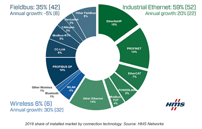
Ethernet-layered protocol used in TCP/IP-based office applications originally presented challenges in the industrial world due to its data packets being broadcast to all nodes over variable pathways with no determined destination time and subsequent latency, which prevented “real-time” data transfer required for machine-to-machine (M2M) communications. Now several Industrial Ethernet protocols have been developed that offer all the benefits of Ethernet but with modifications that provide lower latency and determinism. These include protocols such as Modbus TCP/IP™, EtherCat™, EtherNet/IP™ and PROFINET™. As a result, the use of Ethernet for industrial automation applications is on the rise and is rapidly displacing traditional Fieldbus protocols that are more complex, often proprietary and have limited distance and performance. In fact, Industrial Ethernet is now bigger than traditional Fieldbus and growing at an annual rate nearly four times that of Fieldbuses.
On This Page
- Making Sense of the Buzz
- Industrial Premises are Harsh
- Machines are More Sensitive to Latency
- Ethernet Standards Development for Industrial Premises
- For North America – ANSI/TIA-1005-A
- On the International Front – ISO/IEC 11801-3
- The Big Three – IEC 61158, IEC 61918 and IEC 61784
- Additional Standards to Consider
- Where Do We Go from Here?
Making Sense of the Buzz
 There are plenty of buzzwords in the industrial industry that can cause confusion – everything from Industrial Ethernet and Industrial Internet of Things (IIoT), to Industry 4.0 and smart manufacturing. While Industrial Ethernet is used to describe any Ethernet-based industrial communication protocol, IIoT (which sprung from IoT), Industry 4.0 and smart manufacturing can be used interchangeably in that they all refer the trend that combines industrial production and operations with real-time digital data, machine learning and artificial intelligence. The term Industry 4.0 relates to the fact that this trend could be considered the fourth industrial revolution – the first being the use of hydraulic and steam-powered machinery in the early 1800s, the second being the introduction of steel, electricity and assembly lines in the early 1900s, and the third being the introduction of computer technology into factory environments in the 1960s.
Industrial Ethernet is actually one of the key drivers behind Industry 4.0 and the IIoT as it enables a whole new level of interconnectivity and communication between people and machines as it relates to manufacturing, while providing access to real-time information that will ultimately enable better control and visibility across the supply chain, automated and streamlined maintenance, and improved collaboration and productivity – in other words, smart manufacturing. Because Ethernet protocol is used for transmitting data in the LAN and WAN, Industrial Ethernet also paves the way for better sharing of information between the factory floor and the corporate office. Support also becomes easier, taking advantage of the vast population of Ethernet-savvy IT technicians and tools.
Industrial Premises are Harsh
Traditional Ethernet is usually installed in relatively clean and comfortable environments such as office buildings, schools, and hospitals. Just the opposite is true of Industrial Ethernet. Industrial Ethernet is used in factories and even outside on long conveyors and inside mines. These environments place great stresses on cables. Mechanical stressors include shock, constant movement (robot arms and turntables), and vibration. Ingress situations provide opportunities where moisture and chemicals can get into a cable, while some industries such as food and beverage wash down their equipment (including cables) with hoses daily. Climatic stress results from temperature changes in hot (baking, steel making) and cold environments. Electromagnetic noise from Variable Speed Motor Drives (VFDs), motors, contactors and other equipment can get into Ethernet cables and devices. These ‘MICE’ stressors can be a major cause of Industrial Ethernet cable failures, and the failures can be intermittent and hard to diagnose.
Machines are More Sensitive to Latency
Most people use Ethernet to connect themselves to the web, a wireless access point, a server, telephone, email or printer. Ethernet was designed to move data packets, also called frames, between a person and a device like a printer. Transferring a packet typically takes less than a millisecond. If, for some reason, packets don’t get through the first time, Ethernet will keep trying until the packets get through. This might result in a 2 second delay while printing a 2-page document – and no one would notice or care.
Industrial Ethernet connects machines to other machines running important, time sensitive and sometimes dangerous tasks. Consider a machine controlled by Industrial Ethernet moving a heavy partially assembled vehicle to the next assembly station. As you can imagine, incorrect movements can damage equipment or people or impact quality or production rates. Unlike the printer example, if a few ethernet packets are delayed for even less than one second, the machine must stop to avoid a potential safety issue. It might take hours to put everything back into a safe state and restart the machine – all because of a few lost or delayed packets.
In addition to all the benefits of Ethernet, standards for industrial premises were created to make time sensitive applications running in harsh industrial environments work reliably.
Ethernet Standards Development for Industrial Premises
With Ethernet-based LANs and WANs in the enterprise business world, building a network to industry cabling standards ensures interoperability and cross-vendor support, including support for future applications and leveraging proven installation, verification and maintenance methods that ultimately ensure quality and reliability over the lifetime of the network. Industrial networks are no exception, but as noted above they are much more sensitive to data transmission errors.
When it comes to cabling standards for industrial networks, the Telecommunications Industry Association (TIA) develops standards for North America, while the International Organization for Standardization (ISO) / International Electrotechnical Commission (IEC) develops international standards. Within TIA, the Engineering Committee TR-42 is responsible for developing and maintaining standards for premises telecommunications infrastructure, and due to the need for suppliers to be able to produce standards-compliant connectivity solutions both domestically and internationally, there is strong international participation in this Engineering Committee. In fact, the ISO/IEC WG3 Working Group and the TIA TR-42 Subcommittees share many of the same active participants. In general, TIA standards are well aligned with ISO/IEC standards with some terminology differences. The TR-42.9 Industrial Telecommunications Infrastructure subcommittee deals with cabling standards for industrial environments.
When it comes to industrial automation cabling, all Industrial Ethernet standardization at the international level takes place within the IEC Subcommittee SC65C. A Joint Working Group (JWG) between the ISO and the IEC, Subcommittee 65C/JWG-10 was specifically formed to define wiring and cabling of Ethernet in an industrial environment and to coordinate overlapping domains of premise structured cabling. This group is also responsible for developing and maintaining the Fieldbus installation specifications within the Fieldbus framework of standards.
In addition to TIA, ISO and IEC, there are other regional cabling standards groups such as CENELEC (European Committee for Electrotechnical Standardization), JSA/JSI (Japanese Standards Association), and CSA (Canadian Standards Association) that develop specifications for their geographic area or country. These regional standards groups contribute actively to ISO technical advisory committees and the contents of their standards are usually very much in harmony with TIA and ISO/IEC requirements. In addition to cabling standards, CENELEC also has equivalent Fieldbus standards that are well harmonized with the IEC version.
Now that you know which committees are at work, let’s look at how the specific standards they develop relate to industrial networks.
For North America – ANSI/TIA-1005-A
Published in May 2012, the ANSI/TIA-1005-A Telecommunications Infrastructure Standard for Industrial Premises provides infrastructure, distance, telecommunications outlet/connector configuration, and topology requirements for cabling deployed in industrial environments. TIA-1005-A references the ANSI/TIA-568 family of standards that define structure, topologies and distances, installation, performance, and testing requirements for generic telecommunications cabling, but it specifically includes structured cabling recommendations for industrial environments that are typically subject to harsher conditions and include specialized areas such as automation islands and industrial device areas.
One key aspect of the TIA-1005-A standard is the use of MICE (Mechanical, Ingress, Climactic, and Electromagnetic) method of classifying environments needed to select components for building an industrial network. This includes the following characteristics:
- Mechanical: shock, impact vibration, bending and flexing and crush
- Ingress: particulate size, moisture and immersion
- Climatic/Chemical: temperature, thermal shock, humidity, UV (solar radiation) and chemical pollution
- Electromagnetic: ESD, RF, EFT, transient ground potential, magnetic field
The MICE classifications segment industrial environments into three levels, based upon their degree of severity:
- MICE Level 1: Commercial office environment
- MICE Level 2: Light industrial, such as assembly, food processing, health care, or wash-down areas
- MICE Level 3: Heavy industrial such as petrochemical, foundry, automotive manufacturing or machining
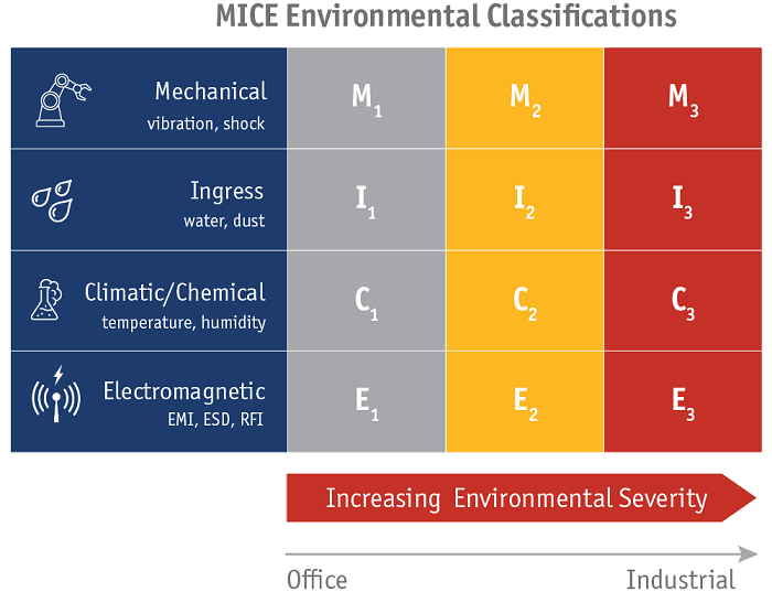
It’s important to note that the level (1, 2 or 3) may not be the same for all MICE characteristics, and in fact any single industrial environment is rarely exclusive to a one classification. For example, while M3I3C3E3 environments require network infrastructure components able withstand the highest levels of vibration, shock, tensile force, impact and bending, a more common classification might be M1I3C3E1 where mechanical and electromagnetic characteristics are no different than a Level 1 commercial environment, but the presence of liquid and chemicals renders the ingress and climatic/chemical classification at a Level 3. The key to using the MICE classification for determining components is to always design to the worst-case scenario.
On the International Front – ISO/IEC 11801-3
ISO/IEC 11801-3 Information technology -- Generic cabling for customer premises -- Part 3: Industrial specifies generic cabling, which is critical for providing robust services to the automation islands in industrial premises, or industrial spaces within other types of buildings. This standard replaces ISO/IEC 24702, which was published in 2006 and specified cabling systems targeted at industrial premises or industrial areas within other types of premises. With the retirement of ISO/IEC 24702, the MICE environmental classification that we also see in TIA-1005-A now resides in ISO/IEC 11801-1 Generic Cabling for Customer Premises – Part 1: General Requirements.
On the whole, ISO/IEC 11801 standards cover cabling systems that are typically used for premise local area networks including both 4-pair balanced twisted-pair copper and fiber optic cabling. In addition to ISO/IEC 11801-3, this includes office spaces (covered in ISO/IEC 11801-2) and data center spaces (covered in ISO/IEC 11801-5). Like the TIA-568 series of standards, the ISO/IEC 11801 family of standards specifies physical media and transmission performance to support various Ethernet speeds.
It should be noted that while ISO/IEC 11801-3 covers cabling to the automation island, it does not address the critical automation, process control and monitoring applications within the automation island itself -- information for this application-specific cabling is provided in IEC 61158, IEC 61918 and IEC 61784 series of standards.
The Big Three – IEC 61158, IEC 61918 and IEC 61784
When it comes to Industrial Ethernet and addressing applications within the automation island, the three most critical cabling standards include IEC 61918 Industrial Communications Networks – Installation of Communications Networks in Industrial Premises, IEC 61784-5 Industrial Communications Network – Profiles, and IEC 61158 Industrial communication networks - Fieldbus Specifications, all of which are controlled by the IEC’s Subcommittee 65C (SC65C).
IEC 61918 standardizes common elements across all the fieldbuses, including those that are Ethernet-based. IEC 61784, which consists of 36 documents, defines a set of protocol specific communication profiles to be used in the design of devices for automation and process control. IEC 61158, which consists of 83 documents, provides guidance and specifications on industrial communication networks, including defining the physical, data link and application layer for Fieldbus and Ethernet-based networks. It also explains the structure of the IEC 61784 series and how to use the standards in combination with each other.
IEC 61784-5 covers several Communication Profile Families (CPF), which specify one or more communication profiles. Divided into subparts for each CPF, the standard specifies which requirements of IEC 61918 apply to each profile and where necessary, supplements, modifies or replaces requirements. Some of the popular Industrial Ethernet profiles covered in IEC 61784-5 include EtherCat, Profinet, Modbus TCP/IP, and EtherNet/IP as shown in Table 1 below.
| 61784-5 CPF | Commercial Name | |
|---|---|---|
| 1 | Foundation Fieldbus HSE | |
| 2 | Ethernet/IP | |
| 3 | PROFInet | |
| 4 | P-NET | |
| 10 | VNET/IP | |
| 11 | TCnet | |
| 12 | EtherCAT | |
| 13 | Ethernet Powerlink | |
| 14 | EPA | |
| 15 | Modbus-RTPS | |
| 16 | Sercos III | |
Table 1.Industrial Ethernet supported profiles.
These three key documents are large and rather expensive, and you really only need the documents that relate to the network you’re deploying. Thankfully, IEC packages the IEC 61158, IEC 61918, and 61784 documents pertinent to the CPF that you are using.
Additional Standards to Consider
In addition to the aforementioned Industrial Ethernet cabling standards, here are some additional standards to consider.
- ISO/IEC 14763-2 Implementation and Operation of Customer Premises Cabling – Part 2: Planning and Installation specifies planning, installation, and operation of infrastructures in support of generic cabling, including the industrial premise. It covers topics such as quality assurance, specification of the installation, installation planning, installation practice, documentation, administration, testing, inspection, operation, maintenance and repair.
- ISO/IEC 14763-3 Implementation and Operation of Customer Premises Cabling – Part 3: Testing of Optical Fibre Cablingoutlines test procedures to be used to ensure that optical fiber cabling, designed in accordance with ISO/IEC 11801 and installed according to the recommendations of ISO/IEC 14763-2, can deliver the level of transmission performance specified in ISO/IEC 11801. This document covers multimode launch conditions, bi-directional OTDR testing, the three-jumper test method, fiber endface inspection and criteria, and the use of reference connectors.
- IEC 61935-1 Specification for the Testing of Balanced and Coaxial Information Technology Cabling – Part 1: Installed Balanced Cabling as Specified in ISO/IEC 11801 and Related Standard specifies comprehensive testing for installed cabling to ensure that the cabling will support telecommunications applications that are designed to operate on the generic cabling system.
Where Do We Go from Here?
As IIoT/Industry 4.0 continue to evolve and industrial applications move towards an increasingly integrated, standardized environment based on Ethernet, we will see additional standards developments and continuing efforts across standards bodies to harmonize, coordinate, and streamline specifications. Already, both TIA and ISO/IEC are in the process of developing standards for single-pair industrial Ethernet applications targeted towards low-complexity, low-speed (i.e., 10Mb/s) M2M communication. Single-pair Ethernet is positioned to significantly cut cost by eliminating unused pairs of a traditional four-pair cabling system and enabling the use of smaller cables and connectors.
TIA’s TR-42.9 Industrial Telecommunications Infrastructure committee is currently developing two addendums to the ANSI/TIA-1005-A standard to address cabling, use cases and topology for single-pair Ethernet applications in the industrial premises. ISO/IEC is currently working on a technical report (TR 11801 9906) that will define the performance of application specific single-pair Ethernet channels. Also in development, amendments to the ISO/IEC 11801 series of standards will cover single-pair Ethernet component and cabling requirements in both generic and premise specific environments, including industrial.
Because typical office-grade cables and connectors are not always suitable for the demands of industrial automation and control environments due to factors such as vibration, electrical noise, equipment in motion, impact dangers, and all manner of sunlight, water, contaminants, and solvents, it’s important to make sure you’re following the right standards specifically developed for the industrial environment. Now that you have an overview of the industrial Ethernet standards environment, we hope it seems less confusing and more manageable – or at least lets you know where to start, which standards documents you need to get your hands on, and which organizations and committees to keep an eye on in the future. Remember that building your industrial network to national or international standards will help ensure interoperability and support for future applications.
With hundreds of different test limits built into our DSX CableAnalyzer Series, you might wonder which of them are based on Industrial Ethernet Standards and can be used in those environments. We recommend that you work with your machine and cabling supplier and your automation equipment vendor specify the right tests and test limits for your installation. Here is some information on the limits built into the DSX based on Industrial Ethernet standards.
The first of these are the TIA-1005 standard for testing channels. Test limits are available for TIA 1005-A channels based on Cat 5e, 6 or 6A. You’ll need to choose the MICE “E” level (1, 2, or 3) for testing electromagnetic susceptibility based on Transverse Conversion Loss (TCL) Measurements. You can also choose to enable additional tests by choosing “+PoE” or “+All”. The “+PoE” tests include a suite of resistance tests which are useful in spotting connectors with high contract resistance which could lead to early failure and intermittent problems in MICE 2 and 3 environments. Using these test limits requires using the channel adapters supplied with the DSX tester (model DSX-CHA004 or DSX-CHA804). As this implies, the TIA-1005 tests are based on a channel configuration, which means that the performance of the connectors at the ends of the link are not tested. If you are field-terminating these connectors, this may not be appropriate.
The second set of test limits are based on the ISO 11801-9902 technical report. Unlike the TIA-1005-A limits, these include the performance of the connectors at each end and are therefore called “End to End link” tests, which is where you’ll find them in the DSX test limits. Similar to the TIA limits, you can choose from Class D, and E, as well as the MICE “E” level. In addition, you also need to specify the number of interconnects in the link (from two to six). Testing the final connector in the link requires a set of optional Patch Cord Adapters that match the class limit you’re testing to (DSX-PC5ES for Cat 5e / Class D, DSX-PC6S for Cat 6 /Class E or DSX-PC6AS for Cat 6A / Class FA). Future amendments of ISO 11801-3 will also include End to End links, and these will be added to the DSX when available.
The third set of limits are designed for PROFINET connections and can be found in the “Application” group in the DSX. There are only two choices – PROFINET and PROFINET 2pr E2E (End to End). These tests, however, use channel adapters, so they may not be suitable for field-terminated end connectors.
Depending on which limits you’ve chosen, you may also need to specify the outlet configuration: whether it’s TIA568A or B wiring, only two pairs, or using a M12 connector (which requires separate optional adapters).
For detailed instructions on how to set up the DSX for various Industrial configurations, visit https://www.flukenetworks.com/industrialethernet/testing-industrial-ethernet-cabling-dsx-cableanalyzer.
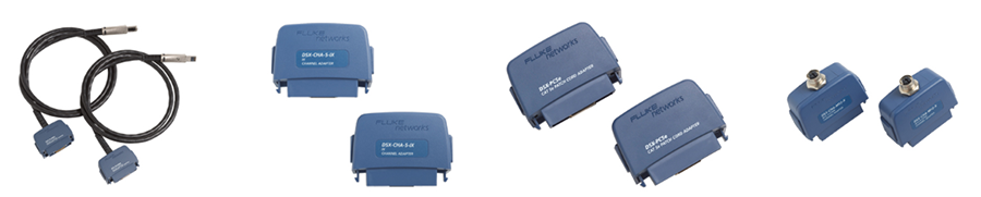
Testing different configurations of Ethernet connections requires the use of the correct adapters. Shown: Permanent Link, Channel, Patch Cord, and M12 adapters