DATASHEET
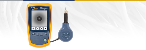
FI-500 FiberInspector™ Micro Fiber Optic End Face Inspection Scope with PortBright™ Illumination
Download PDF
Overview
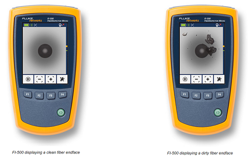
Dirty fiber optic end faces are the major cause of problems in single-mode and multimode fiber optic systems.
The FI-500 FiberInspector™ Micro removes the hassle associated with inspecting fiber end faces, especially in low light and high cable density situations.
It is very simple to use.
Simply plug the cable into the FI-500 and touch the AF button. Within seconds, the fiber end face comes into sharp, clear view. And if you're working in a difficult to reach place or you can't get the image to stand still, just touch the pause button to freeze the image.
On This Page
Just Right for Troubleshooting
Today's high density fiber patch panels make inspection a challenge. Finding the cable or port to test can be tough, especially in the low light conditions found in most data centers and wiring closets.
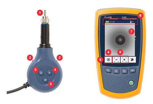
The FI-500 is designed to simplify the inspection process. The built-in PortBright flashlight helps you find the right port or cable. The small-profile probe fits into tight spots, and features push-button controls for simple operation. Autofocus provides a sharp view of the endface in under a second, while the pause button freezes the image on the crisp 320 x 240 display for more detailed inspection.
The FI-500 FiberInspector Micro fills the gap between a manual scope and a fully automated inspection scope. The FI-500 has the simplicity and practicality of a manual inspection scope, but with advanced features to reduce troubleshooting and inspection time.
Manual fiber inspection scopes are simple to use, but they don't work well on patch panels or situations where there is a high density of fiber. Holding it up to one eye and closing your other eye is often inconvenient or impractical, especially in a dark room.
Fully automatic inspection scopes analyze and grade the cleanliness of fiber connections which is important for many applications, but analysis is usually not needed for quick basic troubleshooting.
 |
 |
 |
|
| Important Benefits | Typical Manual Scopes | FI-500 FiberInspector Micro | Typical Analysis Scope |
|---|---|---|---|
| Illumination of small or dark ports | ✓ | ||
| Autofocus for quick and stable images* | ✓ | Model dependent | |
| Compact design to get into tight spaces | ✓ | Model dependent | |
| Works on patch cords and bulkhead connectors | ✓ | ✓ | |
| Wide range of tips to support most connectors | ✓ | ✓ | |
| Capture and zoom to see small particles | ✓ | ✓ | |
| End face analysis to highlight dirt | ✓ | ||
| Image storage | ✓ | ||
| Data transfer to PC or cloud | ✓ | ||
| Rugged digital design | ✓ | ✓ | |
| Relative cost | Low | Medium | High |
*If the APC tip (Angled Physical Contact) is not aligned with connector, the connector or probe may require rotation and repeating autofocus or manual focus.
Fast, Easy Viewing of Fiber End Faces
FI-500 provides immediate and in-depth visibility into fiber patch cords and bulkhead connectors.
-
Screw-on probe tips to support most connector types.
FI-500 includes 4 UPC tips; SC, LC, 1.25 mm and 2.50 mm.
Optional APC tip kit includes 4 APC tips; SC, LC, 1.25 mm and 2.50 mm. Other probe tips available.
-
PortBright built-in flashlight illuminates dark areas and dense panels.
-
Switch on PortBright with a convenient button on the probe.
-
Pause button holds the image for viewing when it's hard to get it just right.
-
Two-second autofocus reduces inspection time and keeps your other hand free. (If the APC tip is not aligned with connector, the connector or probe may require rotation and repeating autofocus or manual focus.)
-
Status bar to see battery charge and other information. Auto power off increases battery life.
-
Bright 320 x 240 backlit display.
-
Magnification of 200X with 1X, 2X, and 4X zoom settings.
- Auto-center moves the fiber ferrule clearly into the frame for precision inspection.
Rugged construction; vibration and drop tested to 1 meter.
Compact design allows you to access dense and crowded panels.
No batteries to change in the probe. Probe is powered by display unit.
Specifications
| General Specifications | |
|---|---|
| Temperature range without the power adapter |
Operating: 0 °C to +50 °C Storage: -30 °C to +60 °C |
| Tenperature range with the power adapter |
Operating: 0 °C to +40 °C Storage: -20 °C to +60 °C |
| Humidity range |
Operating: 0% to 95% °C (0 °C to +50 °C) H non-condensing Storage: 0% to 95% (35 °C to 45 °C) RH non-condensing |
| Altitude |
Operating: 4,000 meters Storage: 12,000 meters |
| Vibration | 2 g, 5 Hz to 500 Hz |
| Shock | 1 meter drop test |
| Safety |
IEC 61010-1 3rd Edition IEC 62133 |
| Display | |
|---|---|
| Magnification | 1x, 2x, 4x |
| Frames per second | ≥12 |
| Battery type* | Rechargeable NiMH, 2 x 1.2V, 2700 mAh |
| Battery life* |
3 hours of continuous probe use 6 hours of typical probe use |
| Charge time | 4 hours minimum |
| Power adapter |
Input: 100 to 240 VAC±10%, 50/60 Hz Output: 6 VDC, 3 A maximum Class II |
| Display | 3.2 inch TFT LCD, 320 x 240 |
| Software upgrades | Upgrades can be installed from a USB drive |
| Input | USB 2.0, Type A |
| Dimensions | 5.5 in x 3.2 in x 1.5 in (14.0 cm x 8.0 cm x 3.9 cm) |
| Weight | 9.7 oz (275 g) |
*Tested using Gold Peak GH230AAHC batteries.
| Probe | |
|---|---|
| Magnification | 200x. Zoom function has 1x, 2x and 4x settings |
| Camera type | 5 Megapixel 1/4-inch CMOS sensor |
| Field of view | 610 μm x 460 μm |
| Resolution | 1 μm |
| Light source | LED, >100,000 hr life |
| End face illumination | Coaxial blue LED |
| Port illumination | 2 white LEDs |
| Power | Supplied through the USB interface |
| Output | Video output through USB 2.0 interface |
| Dimensions |
4.6 in x 2 in x 0.95 in (117 mm x 51 mm x 23 mm) (length depends on adapter tip) |
| Weight | 4.4 oz (125 g)(with no adapter tip) |
Fiber Inspection and Cleaning
Dirt, dust, and other contaminants are the enemies of high-speed data transmission over optical fiber. Today's network applications require more bandwidth than ever, making loss budgets tighter than ever. Hence, it is critical that all optical connections are free of contaminants to avoid having application performance issues.
Eliminate the #1 Cause of Fiber Failure
In a survey of installers and network owners commissioned by Fluke Networks, end face contamination was found to be the leading cause of fiber failures. Dirt and contaminants cause insertion loss and back-reflection that inhibit the light transmission and raises havoc with transceivers. And because dirt can migrate from one end face to another upon mating, both sides of any connection must be inspected. Further, mating contaminated connectors can cause permanent damage as microscopic debris is crushed between end faces in physical contact. Therefore, you must always inspect and clean before mating as a preventative measure and not only after experiencing problems. Even factory-terminated patch cords or pigtails must be inspected as protective caps do not keep end faces clean. Avoiding this common cause of failure starts with inspecting the end face and eliminating any contamination before insertion into a bulkhead or piece of equipment.
Range of Inspection Options
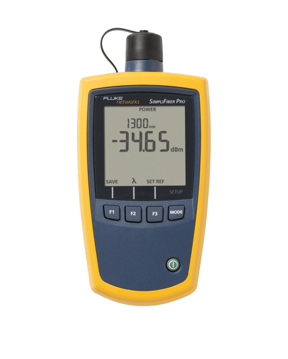
With a range of solutions, Fluke Networks always has the right tool for you to easily inspect endfaces on a wide variety of connectors.
| Fiber Test, Inspection, Cleaning and Certification | SimpliFiber® Pro Test Kits | CertiFiber® Pro OLTS | MultiFiber™ Pro MPO Power Meter | VisiFault™ Visual Fault Locator | Fiber QuickMap™ and OneShot™ PRO | FI-500 FiberInspector™ Micro | FI-7000 FiberInspector™ Pro |
|---|---|---|---|---|---|---|---|
 |
 |
|
|
|
 |
 |
|
| One button operation | ✓ | ✓ | ✓ | ||||
| Locate faults | ✓ | ✓ | |||||
| Fiber length | ✓ | ||||||
| Check connectivity | ✓ | ✓ | ✓ | ✓ | ✓ | ||
| Check polarity | ✓ | ✓ | ✓ | ✓ | |||
| Optical power measurement | ✓ | ✓ | ✓ | ||||
| Encircled flux compliant | ✓ | ✓ | ✓ | ||||
| Dual-fiber loss testing | ✓ | ||||||
| MPO fiber testing | ✓ | ✓ | |||||
| Pass/fail results | ✓ | ✓ | ✓ | ||||
| View fiber bulkhead and end faces | ✓ | ✓ + MPO | |||||
| Capture and analyze bulkhead and end faces | ✓ | ||||||
| PortBright illumination | ✓ | ||||||
| Autofocus | ✓ |