Designing to Application Limits
June 20, 2018 / General, Standard and Certification, Industrial Networks, Best Practices
When it comes to calculating loss budget, it’s important to know the loss limits for the given application as specified by industry standards. But if I really want to know how to design a system to these limits, you also need to know the loss of the specific vendors’ cables and connectivity you plan to deploy—and that can impact exactly which components you specify. This can make the task a bit tricky as not all cables and connectors are created equal.
Let’s take a look at a real-world example.
First Verify the Application
Different fiber applications have different maximum insertion loss requirements to ensure that the loss isn't too high to prevent the signal from properly reaching the far end. So the first task involves determining which fiber application the customer plans to run when the system goes live, and which applications they might plan to run in the future.

Let’s say your customer is designing a data center where they only plan to run 10 Gig over multimode (10GBASE-SR). However, there is a chance that some of the links will need to support 40 Gig in the next year or two. That means you can’t design the system to meet just the 10 Gig limits, which IEEE specifies can be no more than a maximum channel insertion loss of 2.9dB over 400 meters of OM4 multimode fiber.
Considering the customer is planning to migrate some links to 40 Gig, you’ll need to consider those limits in your design. According to the standard, 40 Gig over OM4 multimode (40GBASE-SR4) applications have a maximum channel insertion loss of 1.5dB over just 150 meters of OM4 – quite a bit tighter than the 10 Gig limits.
Then on to the Components
Armed with the channel loss limits for the current and future applications, it’s time to check out the vendor’s loss specifications. Meeting the 10 Gig requirement is relatively easy, since a typical OM4 fiber has a loss of 3dB/km, or 0.003dB per meter, and our example datacenter links are all 100 meters or less. That gives you another 2.6dB for the four connectors in the channel. Let’s say that the customer has specified a vendor (I’m not naming names here) whose MPO-to-LC cassettes specify a loss of 0.6 dB. So we get:
0.3 dB for 100 meters of multimode + (0.6dB X 4) for the MPO-to-LC cassettes = 2.7dB
That’s 0.2 dB below the 2.9 dB standard – close but adequate. Any links less than 100 meters will have additional margin as well.
But when you do the calculation for the potential future 40 Gig applications, you’re going to run into problems. With a total 1.5dB for the channel, you’re left with just 1.2dB for the connectors. Upgrading from 10 to 40 Gig would allow you to swap out the cassettes for MPO adapterswith a little better performance (say 0.4 dB), but you’d still be limited to just 3 connectors in your channel.
That leaves you with some tough choices—either shorten up the longer fiber lengths, limit the number of connectors in the channel, or find a lower loss connector option. Shortening up the fiber links may not work based the design of the datacenter, not to mention that you’d have to limit their length to 30% of the original plan to just meet the spec with virtually no margin whatsoever:
0.09 dB for 30 meters of multimode + (0.4dB X 4) for the MPO-to-LC cassettes = 1.69dB
Deploying three connectors in the channel means customer can have just one cross connect at the core switch and an interconnect at the aggregation switch. Most customers are going to prefer their switch ports to remain completely separate and secure with all moves, adds and changes made at cross connects at both ends of the channel. To make that work, you’ll need two cross connects for a total of four connections.
And this is the reason more vendors are offering low-loss versions of their connectivity solutions. (Pro-tip: low-loss is not synonymous with low-cost.) For example, the vendor noted above offers low loss versions with 0.35dB per cassette and 0.2dB for MPO adapters. With these loss values, you could maintain lengths on all links, deploy four connectors in the channel, meet the design requirement of having cross connects at both switches and design in some margin. Here’s a little basic math:
- 0.3 dB for 100 meters of multimode + (0.35dB X 4) for the MPO-to-LC cassettes = 1.7dB (well below the 2.9dB limit for 10GBASE-SR)
- 0.3dB for 100 meters of multimode + (0.2dB x 4) for the MPO adapters = 1.1dB (still within the 1.5dB limit for 40GBASE-SR4)
Finding an Even Easier Way
As you can see, determining the actual loss for a given application requires knowledge of the standard, the fiber length and number of connectors, the specific vendor’s specified loss for components, and a little bit of basic match. While this is certainly feasible (if you’re diligent), having a vendor-specific link loss calculator takes all the guesswork (and math) out of the equation.
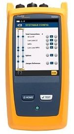
Several vendors offer loss calculators for their components. Fluke Networks’ CertiFiber® Pro Optical Loss Test Set (part of the Versiv™ Cabling Certification System) and LinkWare™ Live cloud service even incorporates CommScope’s SYSTIMAX® link loss calculator for their low and ultra-low loss fiber components right into the tester.
But remember, regardless of what you come up with for your loss budget calculation, the only way to really know if you’ve stayed within budget is to test the insertion loss of the channel after installation via Tier 1 testing using your CertiFiber® Pro. This will be the next step (for the technicians that is).
Testing lets you compare your design calculations to actual results – so you can see how well the installation was carried out since dirty connectors and exceeding fiber bend radius requirements will add even more loss. With the limits loaded into CertiFiber Pro (from the front panel or remotely from your PC and downloaded into the tester), every link tested will be given a PASS or FAIL. The resulting report proves to you and your customer they’re all good. (After you fix and retest any that fail, of course.)
Recent Posts See All >
What Is Fiber Optics? A Guide
2024-03-20
Choosing Stranded vs. Solid Wire Cable
2024-03-06
What Is Return Loss?
2023-02-14
More General Posts See All >
What Is Fiber Optics? A Guide
2024-03-20
Choosing Stranded vs. Solid Wire Cable
2024-03-06
What Is the Right Way to Test an MPTL?
2023-08-22
Explore Our Products
CertiFiber® Pro Optical Loss Test Set


©2006-2021 Fluke Corporation。保留所有权利。
RM2011, 20/F, SCITECH Tower, 22 Jianguomenwai Avenue, Chaoyang District, Beijing, China
地址:北京市朝阳区建国门外大街22号赛特大厦20层2011室
联系电话:400-8103435
沪ICP备11037028号-15![]()