Attenuation and event deadzones - DTX Compact OTDR Module
Quick explanation
- The event dead zone is the approx. minimum distance the OTDR can detect between two events.
- The attenuation dead zone is the approx.minimum distance required to make a loss measurement for an event.
Practically speaking
- The event dead one for the DTX Compact OTDR Module @ 850 nm is typically 3.7 m* with a 20 ns pulse.
- The attenuation dead zone for the DTX Compact OTDR Module @ 850 nm is typically 10 m* with a 20 ns pulse.
*This value is assumes the events have a reasonably low reflectance value; the connection is good. Wider pulses will result in a larger dead zone.
In this extreme example below, a short 20 m link with a bad splice half way was measured. The result is shown below:
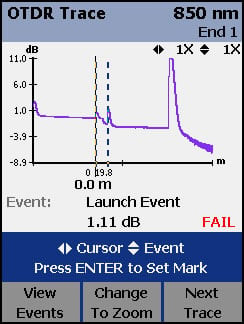
Let's zoom in on the trace:
The permitted loss of a reflective event is 0.75 dB per ANSI/TIA-568-C.1, ISO/IEC 11801:2002 and EN50173:2002 cabling standards; hence the CableAnalyzer reports what it thinks is one reflective event as a FAIL. However, we can still see the splice on the trace and know how to correct the link.
Let's repeat this measurement using the Fluke Networks OptiFiber OTDR, which has a typical attenuation deadzone of 4.5 m.
You may be wondering how we can have 0.0 dB loss for a mated connection. In this example, the backscatter coefficient of the launch cable is different to that of the fiber under test. Combined with an excellent mated connection, the result is 0.0 dB. On occasions, you may see a small negative value here. In the OTDR world, this is normal. To overcome this, you may wish to do bi-directional testing.
Do you have  installed on your PC? If so, you can download the examples above for a more detailed view.
How is the event dead zone defined?
- Measure at 1.5 dB below a non-saturating reflection peak for a typical UPC connector
(<-40 dB multimode and < -50 dB singlemode using 20 ns pulse width)
How is the attenuation dead zone defined?
- Measure at ±0.5 dB beyond backscatter for a typical UPC connector
(<-40 dB multimode and < -50 dB singlemode using 20 ns pulse width)
Reflectance has a significant influence on deadzones. Usually, the lower the reflectance, the smaller the deadzone. When evaluating various OTDRs, it is important to know what reflectance is used for the deadzone specifications. Most OTDR suppliers will specify deadzones with a reflectance of - 55 dB for singlemode. Some suppliers specify multimode deadzones with a -45 dB reflectance. This can be misleading, because a -45 dB reflectance for multimode is better than a typical UPC polish. (As noted above, Fluke Networks uses -50 dB and -40 dB respectively when defining the dead zones). When the manufacturer specifies deadzones under better conditions than you can expect to find in the real world, the deadzones you actually encounter with their equipment will be longer than they specify. This is why we emphasize real world performance in this article.