WHITE PAPER
Encircled Flux - Solving the Puzzle of Repeatable Fiber Loss Testing
Download PDF
Overview
More and more manufacturers are requiring Encircled Flux testing as a condition for support and warranties. Find out why EF is moving from a recommendation to a requirement.
On This Page
The key to reducing uncertainty between multimode fiber light sources
In the past, users have been confronted with variations of up to 40% when measuring loss on the same multimode fiber using two different manufacturer's testers. Encircled flux (EF) is a metric that defines the launch conditions on multimode optical fiber. Manufacturers of optical fiber power loss testers are now required meet the new EF compliance standards to reduce measurement uncertainty in link loss measurements between different manufacturer's test equipment.
Encircled flux (EF) compliance of LED (light emitting diode) sources is required for fiber test equipment in ANSI/TIA-568.3-D and ISO/IEC 11801:2011 Edition 2.2 for Optical Power Loss Measurements of installed Multimode Fiber Cable Plant.
The use of EF compliant sources was first introduced in TIA-TSB-4979, Practical Considerations for Implementation of Encircled Flux Launch Conditions in the Field.
This article describes the EF testing method and the practical considerations for implementing the method. There are now four pieces to the jigsaw puzzle that make for a successful Tier 1 optical loss measurement: LED source, proper setting of the reference, reference grade connectors, and EF as the final piece. Each of these pieces must be done correctly to achieve optimum results.
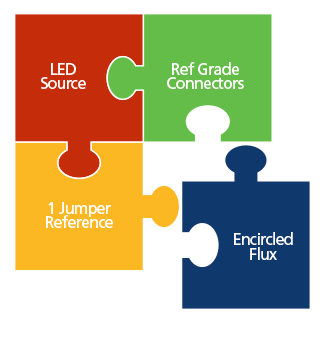
Figure 1: Encircled flux (EF) is the final piece of the puzzle for successful Tier 1 Optical loss measurement.
The Source
When testing multimode optical fiber links, the user theoretically has the option of testing with either a vertical cavity surface emitting laser (VCSEL) or an LED. However, ANSI/TIA-526-14-B specified the source must have a spectral width of between 30 nanometers (nm) and 60 nm, which is easily achieved with an LED source. A VCSEL source has a spectrum within the region of just 0.65 nm, which is not even close to the required 30 nm, making its use a violation of some industry standards. Previous standards included clauses that allowed the user to use a VCSEL, but those clauses have been removed, and VCSELS are no longer allowed. The reason for this is the VCSEL launch into optical fiber varies substantially between different VCSEL sources, increasing measurement uncertainty to a point where it is no longer acceptable. The VCSEL launch is also under filled, resulting in an optimistic loss measurement reading (more on this below).
Some argue the light source used for testing should be the same as the light source of the active equipment. This is not a bad idea if we dismiss the measurement uncertainty associated with using a VCSEL and the loss values defined in IEEE 802.3 for 10GBASE-SR that are based on an LED source. More important, however, is whether or not cabling vendors will accept an application warranty if the optical fiber system is tested with a VCSEL. Most will not, due to the uncertainty of the measurement. That is why most test equipment vendors no longer offer a VCSEL option for customers. As with all cabling standards, it is the responsibly of the individual testing and warranting the system to ask what type of source is to be used when testing. If in doubt, review the test equipment vendor's data sheet and verify requirements with the vendor offering the warranty for the cabling system.
The Reference
Setting the reference incorrectly can lead to optimistic and negative loss results. Negative results are the largest cause for failed system acceptance and denial of warranty. A negative optical loss suggests an amplification of the optical signal, which is impossible in a passive system. Sadly, many technicians still set a reference through a bulkhead adapter and then simply connect to the optical fiber under test (see Figure 2).
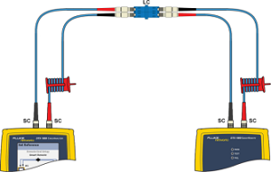
Figure 2: Setting a reference through a bulkhead adapter is an incorrect method.
It is essential to follow the industry standards and set a reference using a single test reference cord. Many know this as the 1 Jumper Method of Method B for multimode optical fiber and Method A.1 for singlemode optical fiber. When setting a reference using a bulkhead adapter as shown in Figure 2, measurement uncertainty starts with whatever the loss is in that bulkhead adapter. Since there is no way to know that loss, measurement uncertainty could be as high as 1.5 dB.
The loss in the bulkhead adapter is removed from the loss measurement, which is how the results indicate a negative loss. One can get around this by adding a short jumper after setting the reference, but that can add more uncertainty to the measurement.
The optical fiber in Figure 2 is coiled around a mandrel. If not using a mandrel, the results will be pessimistic by up to 0.4 dB and probably unstable depending on whether the source is over filled or under filled. Consequently, perfectly good links could be showing a false fail.
Another common problem is the use of bend insensitive multimode fiber (BIMMF) test reference cords. These are not suitable for use with dual wavelength testers. With BIMMF, the standard 25 millimeter (mm) mandrel will not strip out the higher order modes at 850 nm resulting in pessimistic 850 nm losses. It will perform as if there was no mandrel at all. A 4 mm mandrel could be used but then 1300 nm measurements will be incorrect.
To achieve reliable measurements, optical fiber test equipment that has interchangeable adapters on the input ports is required. This allows for setting a 1 Jumper Reference in accordance with TIA and more importantly, in accordance with the cabling vendor requirements since they issue the cabling warranty. It is also important to purchase the correct adapters and test reference cords to go with them. Too many installers have the correct optical fiber equipment but not the right adapters or hybrid test reference cords.
Fluke Networks has also produced an automated wizard on the CertiFiber™ Pro to walk technicians through the reference procedure process with the use of animated setup screens (see Figure 3). This should help installers correctly set reference using the one jumper method.
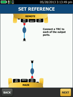
Figure 3: To address poor referencing, test equipment vendors are creating automated wizards to walk the technician through the reference procedure process
Reference Grade Connectors
Poor quality test cords lead to poor and inconsistent test results. Testing of Optical Fiber Cabling requires a multimode optical fiber reference grade connector to have a loss of <0.10 dB. Why such a low value? In ISO/IEC 14763-3, the first and last mated connections must have a multimode loss of <0.3 dB and a singlemode loss of <0.5 dB, which can only be achieved with reference grade connectors. But there is more to what the standards say. With the introduction of low-loss (<0.35 dB) multifiber push-on (MPO) to LC modules, the connector at the end of the test cord needs to be better than the 0.5 dB most have become accustomed to using. The low loss of <0.35dB is achieved by having an LC connector rated at <0.15dB. Consequently, if the test cord is not <0.15 dB, chances of hitting the <0.35 dB loss for the module are slim.
If using a 1 Jumper reference, the test reference cords can be verified. Once the 1 Jumper reference has been made, the cords are removed from the input ports. A quality cord is then inserted into the input ports, the main and remote units are joined together using a singlemode rated bulkhead adapter and the test is run. The loss result should be saved and become part of the system documentation. Anyone reviewing the test results will have increased confidence in the measurements. It will also reduce finger pointing if two tests were done on different days with different outcomes. Using a 1 Jumper reference and verifying the test reference cords dramatically improves the consistency of optical loss testing. However, there is one final element that can still result in a 40 percent uncertainty between different test equipment vendors: the launch of the optical source into the optical fiber. That is where EF comes in as the missing piece of the puzzle.
Encircled Flux
You would expect setting a 1 Jumper reference and verifying the test reference cords at <0.1 dB would result in the same outcome even if using different vendors' equipment. Unfortunately, it does not. TIA standards have always defined the launch condition from a multimode optical source in the form of coupled power ratio (CPR) to reduce the measurement uncertainty caused by different light sources.
To correctly specify the launch condition of a source, in the new standards the entire 50 μm end face needs to be specified, not just the 5 µm in the middle. EF specifies the modal power across the entire end face of the launch with the use of template. One important point is that EF has to be met at the end of the test reference cord. Modern production techniques allow an EF compliant source without too much trouble. The challenge is that when adding the test reference cords, the EF template must be maintained to the end of the test reference cord.
TIA-TSB-Standards call out two options for meeting EF requirements. The first is to use an external launch conditioner. This has one critical advantage in that it can turn any LED source into an EF-compliant solution, avoiding the need to buy new test equipment. However, push back is inevitable when users discover the high expense of external launch conditioners, their bulkiness and the need to replace them when the connector at the end breaks.
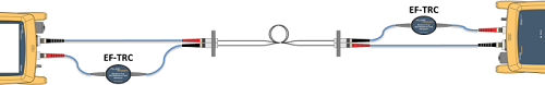
Figure 4: The most straightforward way to achieve EF launch conditions is with a compliant source and tuned test reference cords (TRCs).
The TSB gives the user a second option where the optical source is EF compliant and a tuned test reference cord is attached to the source (shown in Figure 4). This is a proprietary solution, but the cords are less expensive than launch conditioners and less bulky. However, it does require the purchase of new test equipment. If existing test equipment has fixed input ports that do not allow a 1 Jumper LC reference, it would make sense for installers to jump two generations of testers, making testing of optical fiber both EF and 1 Jumper compliant in accordance with the new standards at the same time. Fluke Networks have produced EF compliant Test Reference Cords (TRCs) to be used in conjunction their EF compliant testers to achieve reliable and repeatable measurements.
Conclusion
EF has a real impact on system acceptance, especially if installing low-loss components. Operating to custom loss budgets based on the specification given by the vendor will result in ever-tightening margins. Installers are now required to be EF compliant in their optical fiber testing, so take a look at your field test procedures and ensure that your installers are following these current best practices:
- Do not set references through bulkhead adapters.
- At the very least, use mandrels to remove higher modes, but remember that mandrels are not a substitute for EF adapters.
- Use LEDs, not VCSELs, as the light source to avoid optimistic results.
- Invest in optical fiber test equipment with interchangeable adapters on the input ports.
- Verify test reference cords and do not use BIMMF as a test cord.
- Make sure to save measurements and make them part of the documentation.
- Ensure your procedures and test equipment are EF compliant, whether using launch conditioners or selecting a proprietary solution. Keep in mind that vendors are now starting to insist on a 1 Jumper EF-compliant measurements before sending an engineer to troubleshoot a failing system. Installers will need to be ready and able to provide this information.
EF is now a requirement as per ANSI/TIA-568.3-D and ISO/IEC 11801:2011 Edition 2.2 – it is not a method made up by test equipment manufacturers. There is a difference in the launch conditions between different sources. Although there was some confusion over EF when the metric was first discussed, there is now complete agreement in the industry over the methodology and the proper test equipment. Up until the last few years, there was no need for a precise method and metric to define a predetermined launch condition from a multimode optical fiber source. But with tighter loss budgets and higher data rate systems, EF is now a key measurement consideration.
Fluke Network EF Compliant Optical fiber loss testers
CertiFiber® Pro – Accelerates every step of the fiber certification process
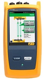 The CertiFiber Pro improves the efficiency of fiber certification with a 3 second, two fibers at both wavelengths test. Integrates with LinkWare™ Live to let you manage jobs and testers from any smart device over Wi-Fi. The Taptive user interface simplifies set-up, eliminates errors and speeds troubleshooting. A set reference wizard ensures correct reference setting and eliminates negative loss errors. Built on the future-ready Versiv™ platform, CertiFiber Pro provides merged Tier 1 (Basic) / Tier 2 (Extended) testing and reporting when paired with OptiFiber Pro module. A convenient quad module supports both singlemode and multimode and is multimode Encircled Flux compliant. Copper certification (up to Cat 8), OTDR, and automated fiber endface inspection modules are also available. Analyze test results and create professional test reports using LinkWare Management Software.
MultiFiber™ Pro Optical Power Meter and Fiber Test Kits
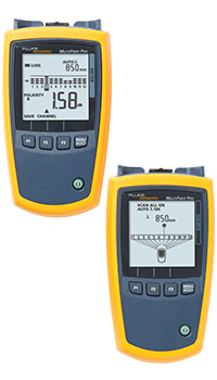 MultiFiber Pro tests MPO fiber trunks without the use of fan-out cords, eliminating the complexity of polarity issues and making cassette testing in the field much easier.
Whether it is using 10 Gbps pre-terminated fiber trunks or planning for next-generation 40/100 Gbps performance, data centers are standardizing on an MPO connector solution. Typical fiber installation means time-consuming, manual and imprecise MPO validation. MultiFiber Pro is 90 percent faster than the single-fiber testing method because it measures power loss and validates polarity on 12 fibers in a single connector— reducing test time from weeks to days. Singlemode and EF compliant multimode versions are available.
SimpliFiber® Pro Optical Power Meter and Fiber Test Kits
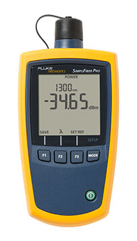 With new advanced capabilities that make testing simple, SimpliFiber Pro Optical Power Meter and Fiber Test Kits are the best “go-to” kits for anyone involved in first-line optical fiber cabling installation and verification. Whether you are a fiber technician or contractor, our expertly configured kits contain all the tools necessary to quickly measure loss and power levels, locate faults and polarity issues, and inspect and clean connector end-faces. Industry-leading features such as single-port dual-wavelength testing and auto-wavelength detection, combined with time-saving capabilities such as CheckActive™, FindFiber™, and Min/Max make SimpliFiber Pro the best fiber test kit on the market.