Test reference cords (TRCs) vs. patch cords
There are two types of fiber optic patch cords. Those used for testing fiber optic systems, the other for normal day to day patching. So what's the difference?
Test Reference Cords (TRCs)
TRCs are used for certifying cabling systems to ANSI/TIA, ISO/IEC and IEEE standards. They are terminated with reference grade connectors per ANSI/TIA-526-14-C and IEC 61280-4-2. These standards specify multimode connectors having a mated loss of ≤ 0.10 dB. The TIA version for singlemode does not specify it at this time but can be found in ISO/IEC 14763-3, where again a reference grade connector must be used having a mated loss of ≤ 0.20 dB.
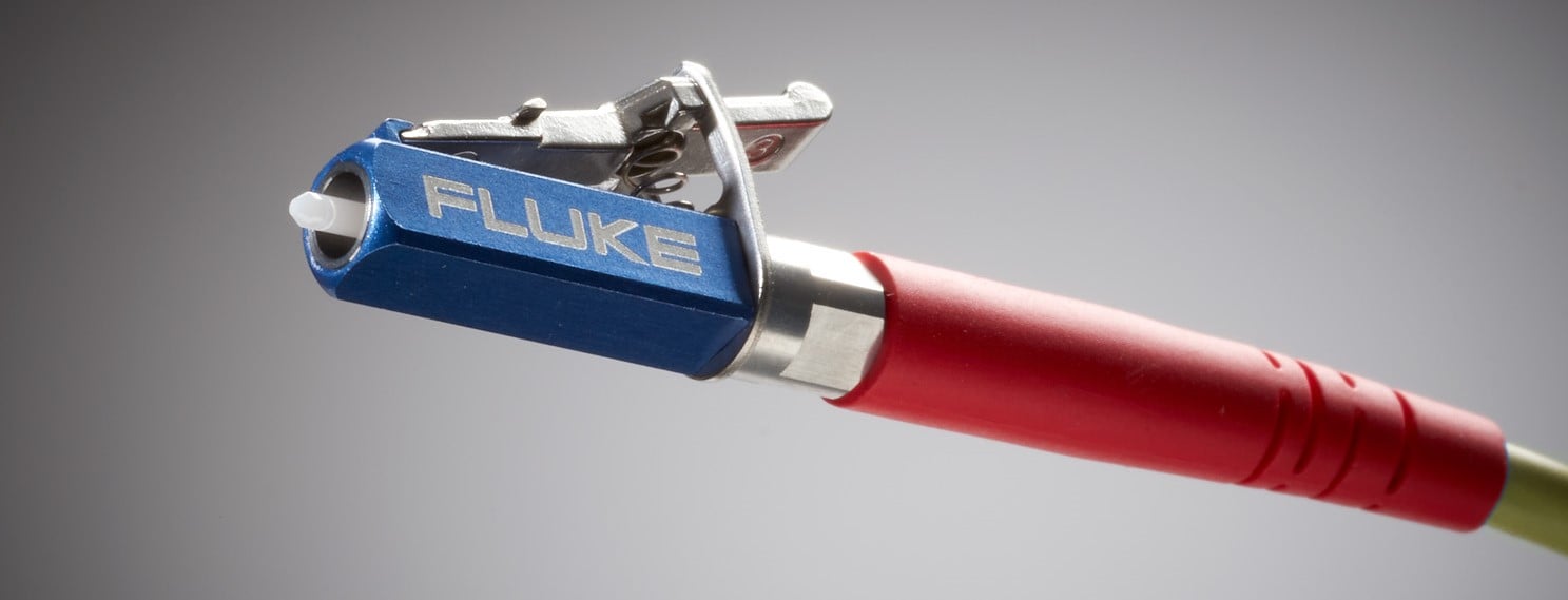
Fluke Networks TRC's feature our durable Metal LC connector. Learn More
Why use a TRC? If you are installing low loss connectors, those connectors may have a loss of ≤ 0.15 dB. So testing it with a connector that has a loss greater than 0.15 dB will yield a pessimistic result. More importantly, if your link is an engineered link operating to custom test limits - you could be failing a perfectly good link. Another advantage is consistent and predictable results - something installers often complain about when certifying a cabling system.
Patch Cords
Patch cords are by definition used for anything other than testing. The current ANSI/TIA and ISO/IEC requirement for a mated loss is ≤ 0.75 dB. So if the patch cord connection meets 0.75 dB, you can say they are ANSI/TIA or ISO/IEC compliant. Almost all vendors use ≤ 0.50 dB for a maximum mated loss in production. (Excluding singlemode MPO)
Is it possible to make a Test Reference Cord in the field?
If you are required to be Encircled Flux compliant, you cannot make your own TRCs. If you do not care about Encircled Flux, it's not impossible of course to make a TRC, but extremely difficult. You will struggle to find a vendor even willing to make them – that is how difficult they are to make. Hence the price premium. For detailed specifications on Fluke Networks' TRCs, click here.
If you decide to make your own multimode TRC, make sure the fiber is not Bend Insensitive Multimode Fiber (BIMMF). Wrapping a BIMMF cord around a standard 25 mm mandrel will fail to strip out the higher order modes @ 850 nm, resulting in pessimistic readings. To strip out the higher order modes @ 850 nm, you would have to use a 4 mm mandrel. Doing so will then degrade your 1300 nm measurement! With the industry moving to BIMMF, you may struggle to find non BIMMF fiber. This has become a common support call issue into the Fluke Networks Technical Assistance Center.
Is it possible to make a patch cord in the field?
Yes. BUT, if you are field polishing, don’t expect the reflectance to be good. Field polishing is a really bad idea for singlemode, where reflectance is often an overlooked parameter affecting network performance. This is also true for high speed multimode systems. If you are going to make your own cords, you should look to a mechanical connector to terminate the cord with. Examples include but are not limited to the Corning UniCam®, CommScope Quik II, TE LIGHTCRIMP Plus™ and Panduit OPTICAM® connectors.
Verification of Test Reference Cords in the field
This should be done as part of your standard operating procedure throughout the day. Agree to do this after 288* fiber tests to ensure the TRCs have not degraded in performance. The CertiFiber Pro has an automated wizard that walks you through this process and records the TRC values. You can do this with the DTX CableAnalyzer too, but the process is manual. An example for the DTX CableAnalyzer can be found here (Look to step 25). Doing this will ensure predictable, accurate test results. If your link should fail, you will know it is not caused by poor test reference cords.
* If you are operating in a dusty/dirty environment, you may need to increase the frequency of TRC verification.
All Videos in This Series

Related Products
FI-7000 FiberInspector™ Pro
CertiFiber® Pro Optical Loss Test Set
OptiFiber® Pro OTDR Family
SimpliFiber® Pro Optical Power Meter and Fiber Test Kits
LinkWare™ PC Cable Test Management Software