APPLICATION NOTE
Mode Conversion Testing Prevents Your Network from Hanging in the Balance
Download PDF
Overview
There is a reason that balanced twisted-pair copper cabling is used for today’s high-speed Ethernet networks, and that reason is balance. Noise immunity is an important factor in the ability of a cable to properly transmit Ethernet signals, and the balance of the two conductors in a twisted pair is what cancels out noise injected into the cable. Balance is also responsible for preventing signal leakage from the cable. As we move to higher frequencies and faster data rates, cables are even more sensitive to noise, and ensuring good balance becomes more vital than ever.
Balance in twisted-pair cables is achieved through the overall design of the cable and precise manufacturing. However, not all cables are the same and there is plenty of variability in the marketplace. Ensuring balance of a twisted pair through mode conversion testing is an excellent indicator of noise immunity, including alien crosstalk (AXT) in higher frequency applications. However, mode conversation testing is not currently a field test requirement per industry standards due to lack of field test equipment able to perform these tests. Installers and end users in the field have had no means to verify balance—until now.
On This Page
Why Balance Matters
The basic concept behind balance is that Ethernet signals are applied in differential mode to the two conductors of a pair as opposite positive and negative voltages, otherwise known as out-of-phase. In differential mode, the two signals reference each other. This differs from common mode where the signals appear in-phase and are referenced to ground.
Common mode signals can be partly converted to differential mode along the transmission path of a data link and vice versa. Referred to as mode conversion, this phenomena can occur within a pair or between pairs, and it’s not a good thing. When noise is injected into a cable in common mode, a percentage of that noise can be converted to differential mode and become part of the Ethernet signal. The imbalance caused by this noise in turn causes the voltage on the balanced pairs to be unequal, degrading the differential signal of Ethernet transmission with the potential for bit errors, retransmissions and slower network performance. Mode conversion can be particularly problematic in Industrial Ethernet and data center applications where the environment is noisy and latency is critical.
Balance is achieved through the overall design of the cable and precise manufacturing that results in tighter, more consistent pair twists with equal sizing and spacing of the conductors. A well balanced cable offers better noise immunity in that the induced common mode noise will appear as equal or nearly equal voltage on the balanced pair and hence be cancelled out.
Figure 1 below demonstrates the difference between a link with good balance and a link with poor balance. In the link with good balance, the injected mode is seen as equal and the differential mode signal remains the same voltage at the other end of the link. In the link with poor balance, the injected mode is not seen as equal by both conductors, resulting in unequal differential mode voltage at the far end.
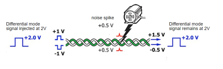
Link with Good Balance
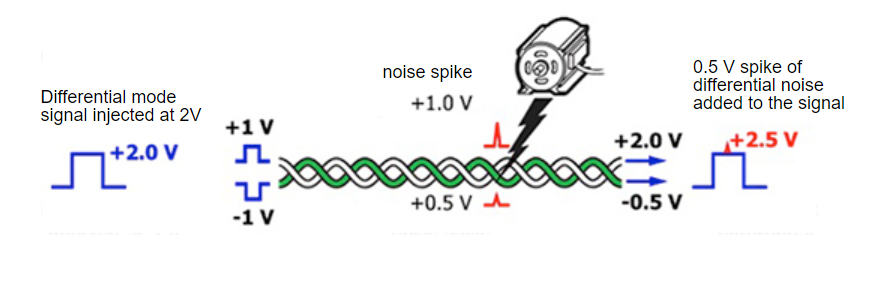
Link with Poor Balance
Figure 1 below demonstrates the difference between a link with good balance and a link with poor balance. In the link with good balance, the injected mode is seen as equal and the differential mode signal remains the same voltage at the other end of the link. In the link with poor balance, the injected mode is not seen as equal by both conductors, resulting in unequal differential mode voltage at the far end.
TCL and ELTCL Mode Conversion Parameters
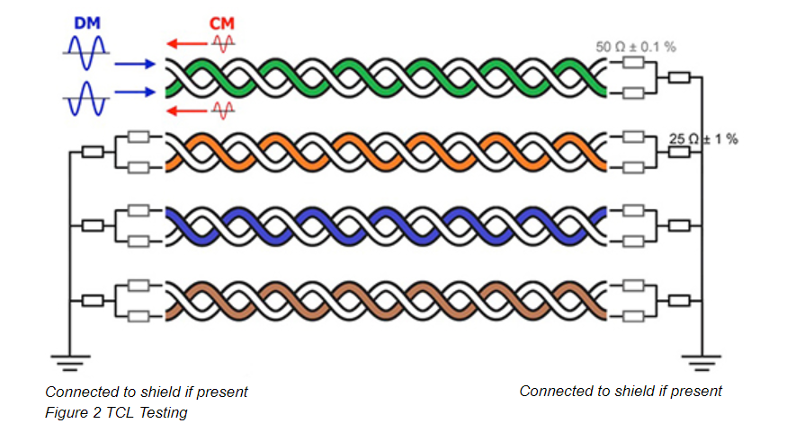
ANSI/TIA-568-C.2, ANSI/TIA-1005 and ISO/IEC 11801:2010 includes two mode conversion parameters that indicate balance—TCL and TCTL. Transverse Conversion Loss (TCL) is mode conversion measured within a pair at the same end. As shown in Figure 2, it is measured by injecting a differential mode signal into a twisted pair and then measuring the common mode signal returned on that same twisted pair. The smaller the common mode signal returned, the better the balance. TCL seems similar to a Return Loss measurement, except that rather than measuring the common mode signal returned, Return Loss measures the differential signal returned.
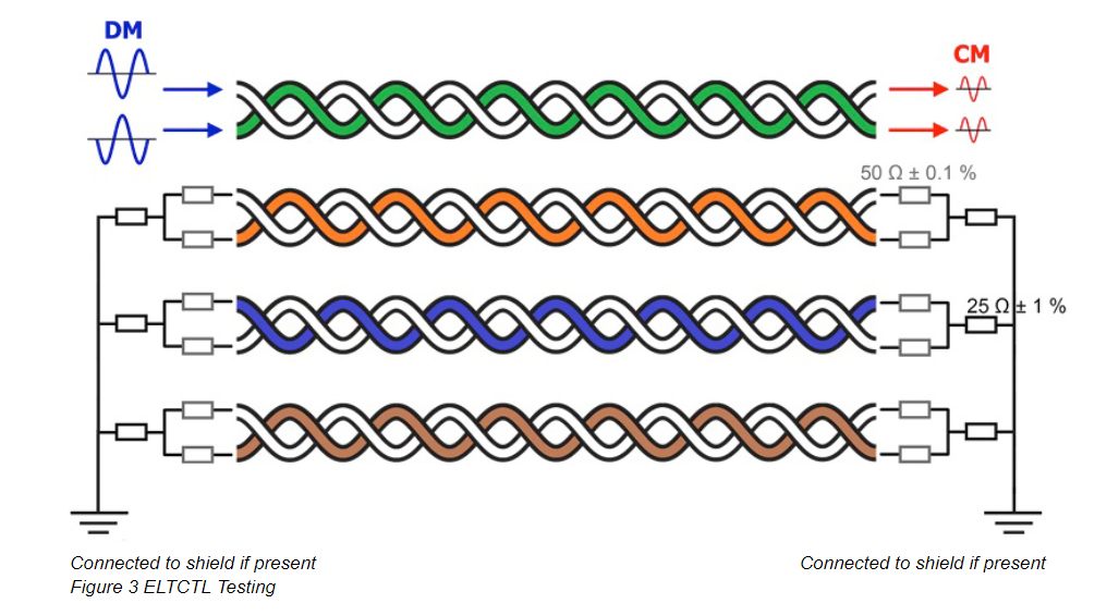
Transverse Conversion Transfer Loss (TCTL) is mode conversion within a pair measure at the opposite end. As shown in Figure 3, it is measured by injecting a differential mode signal into a twisted pair and then measuring the common mode signal at the other end of the link on that same twisted pair. Since the amount of common mode signal is length dependent, equalization must be applied to take insertion loss into account. Therefore the more meaningful measurement is Equal Level TCTL (ELTCTL). Similar to TCL, the smaller the common mode signal at the far end, the better the balance.
Just as TCL looks similar to a Return Loss measurement, ELTCTL looks similar to an Insertion Loss measurement. However, Insertion Loss measures the differential mode signal at the far end while ELTCTL measure the common mode signal at the far end (TCTL) and then applies equalization based on Insertion Loss to acquire the ELTCTL measurement.
While TCL and ELTCTL parameters are excellent indicators of the balance of a twisted-pair cable, neither is currently a field test requirement under ANTI/TIA-568.C.2 standards. This is because most field test equipment has only been capable of differential mode measurements. TCL and ELTCTL testing have therefore been limited to laboratory environments by manufacturers who must ensure good pair balance characteristics to comply with TIA and ISO/IEC industry performance standards.
But let’s face it—not all cables are the same and there is plenty of variability amongst design and manufacturing consistency. Furthermore, balance is something that manufacturers typically comply with only through initial quality testing of their products and not necessarily throughout the ongoing day-to-day manufacturing process, which can experience irregularities.
Because TCL and ELTCTL are important measurements that define a minimum performance for balance and therefore noise immunity, there is a growing interest in these parameters among network owners/operators. Rather than relying solely on manufacturer claims, balance can now be verified in the field with the DSX CableAnalyzer (see sidebar). The DSX is the first field tester capable of both differential mode and common mode measurements to support balance testing via TCL and ELTCTL.
Striking a Balance with ANEXT
At the higher frequency of 500 MHz required to support 10 Gb/s data rates such as with 10GBASE-T, AXT, the unwanted noise coupling between neighboring cables, becomes the limiting factor in transmission performance. That is why higher performance category 6A cables required to support 10 Gb/s are designed with better pair-to-pair balance to provide improved noise immunity over lower category cables.
In the laboratory environment, cable manufacturers test for AXT by using a six-around-one cabling configuration, which provides the worst-case scenario for a cable surrounded by six disturber cables. While this is fairly straightforward, field testing for AXT is a much more complex process. Rather than testing each cable within a bundle, which would be extremely time consuming, practical field certification involves sampling only a percentage of the total number of links, typically 1% or five links. It is also recommended to test the longest and shortest links in a bundle since those tend to exhibit the highest AXT levels. Despite the sampling method, AXT testing is rarely performed in the field and often not required by manufacturers for certification.
While few have deployed 10 Gb/s speeds outside of the data center environment, 10GBASE-T is expected to make its way into the enterprise space over the next few years. It is therefore becoming more critical than ever to ensure AXT performance. However, the labor costs associated with field testing for AXT are still a concern, especially for large installations with thousands of links. Because much of the previously installed category 6A cabling was not originally tested and certified for AXT, there is no actual way to know if the existing cabling has the AXT performance to support 10GBASE-T.
Luckily balance as determined via testing for TCL and ELTCTL is an excellent indicator of whether or not a cable will provide adequate AXT performance to support 10GBASE-T. Testing for TCL and ELTCTL is a much easier parameter to test for than AXT as it can be accomplished alongside standard field testing for other required in-channel performance parameters (i.e., NEXT, PSNEXT, insertion loss, return loss). In fact, TIA recognizes the strong correlation between balance and noise with TSB-1197, which explains the interaction between balance and mode conversion parameters within a channel and alien crosstalk between channels.
Conclusion
No one can dispute the fact that noise immunity and therefore good AXT performance can be achieved without good balance. With many existing category 6A systems having never been tested for alien crosstalk, and few manufacturers requiring AXT testing, there is no way to know if these installed cables have adequate balance performance to support 10GBASE-T. Testing for TCL and ELTCTL therefore offers significant advantages for both installers and end users.
Whether or not the TCL parameter is eventually required by the standards remains to be seen. While not currently a requirement for compliance with ANSI/TIA-56-C.2, the ability to easily test for TCL and ELTCTL using the DSX CableAnalyzer makes it possible to now verify balance and support for higher speed applications like 10GBASE-T through regular field testing. It’s one of the easiest, most effective ways to ensure that your network performance doesn’t hang in the balance.
What About Balance on Shielded Cabling?
While LAN cabling is predominately unshielded, shielded cabling is often deployed as a means to provide noise immunity in many environments and touted as enabling better performance for high-speed applications. Many argue that alien crosstalk is not a concern with shielded cabling. However, the shield needs to remain continuous throughout the entire channel to ensure good alien crosstalk performance for high speed applications. Balance on shielded cabling tends to be less controlled than unshielded cabling, because the introduction of the screen can reduce coupling of external noise sources to the signal pairs in the cable. While TCL and ELTCTL parameters become less important with shielded cabling, the integrity of the screen itself is critical to the performance of shielded cabling.
An excellent method of ensuring shield integrity is to utilize the shield integrity option on the DSX CableAnalyzer. Shield continuity historically is a direct current (DC) measurement with no distance to fault available. In the data center environment where both ends of the cable reside in racks that are grounded to the building and hence have a common ground, using a DC measurement will show that the shield is connected even when it isn’t. The DSX CableAnalyzer is the first field tester to report distance to shield integrity issues using a patented alternating current (AC) measurement technique, indicating a break in a shield regardless of common ground and pinpointing the exact location of the break.
Testing for TCL and ELTCTL is Fast and Easy with DSX
TCL and ELTCTL is not a field test requirement because until the DSX CableAnalyzer came along, no field test equipment could perform a TCL field test. While the parameter may eventually be required in field testing per industry standards and other test equipment vendors will also eventually offer TCL field measurements, most field testers on the market are normally capable of differential mode measurements only. The DSX CableAnalyzer is capable of both differential mode and common mode, measurements, hence its ability to measure TCL and ELTCTL.
TCL and ELTCTL can be easily added to standard category 5e, 6, 6A or Class D, E or EA testing by selecting the test limit under the folder in DSX called Balance Measurements and looking for the test limit with a suffix of (+TCL) as shown below:
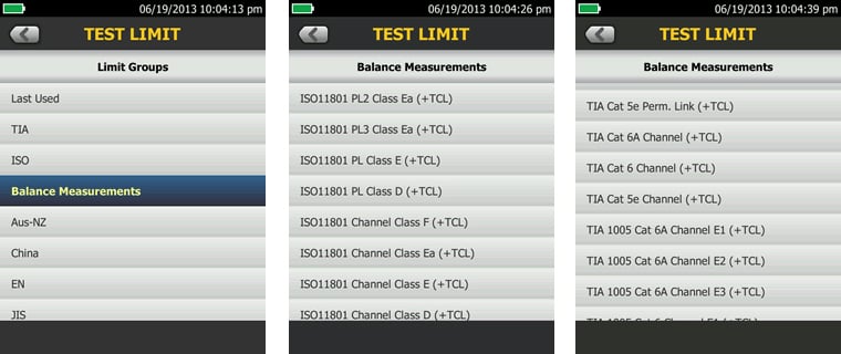
The suffix of (+TCL) indicates a standard ANSI/TIA or ISO/IEC test with the addition of TCL and ELTCTL measurements. ANSI/TIA-568-C.2 and ISO/IEC 11801:2010 only provide test limits for channel measurements at this time. If you select a permanent link test limit, the TCL and ELTCTL measurements will be performed, but no PASS/FAIL criteria will be applied. Industrial Ethernet standards TIA 1005 with the different E1, E2 and E3 environmental TCL and ELTCTL limits are also provided. Testing for TCL and ELTCTL adds only about 6.6 seconds to the typical DSX AUTOTEST time—a very short amount of time compared to AXT testing and time well spent to verify balance.