OTDR: Your Ultimate Troubleshooter
February 28, 2018 / General
So you’ve finished your fiber cable installation and are now on to the task of certifying the cable plant using an optical loss test set (OLTS) – it’s the tool you need for Tier 1 certification and the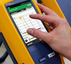 most accurate for measuring loss to ensure application support.
Unfortunately, you find some critical fiber links that far exceed your loss budget for the application. You now need to troubleshoot those links so you can fix the problems and move on to your next job. And the faster you can locate the problems, the faster you can fix them.
Your OLTS can’t tell you exactly where the loss is happening along the link, and you simply don’t have the time to inspect each failed links’ connectors for contamination or try to visually locate a potential break (which could be anywhere) using a visual fault locator (VFL). But if you’ve got an optical time domain reflectometer (OTDR), you can rest assured. It is, after all, the ultimate troubleshooting tool.
Reflections Tell You More
Problems with your fiber links can be caused by microbends, kinks and breaks somewhere along the fiber, contaminated connectors, faulty fusion splices and a variety of other field termination, cable management or installation mishaps. Thankfully your OTDR has the ability to detect reflected light, or backscatter, to locate and measure the loss of any of these events. Access to this level of detail with an OTDR also arms you with a complete picture of the fiber installation and the overall quality of the workmanship.
Even if the application will only use the lower wavelength for transmission, when troubleshooting with your OTDR, it’s best to test at both the 850 and 1300nm for multimode and 1310 and 1550 for singlemode. Normally, the higher wavelength would show a lower loss, but if the fiber is stressed, the higher wavelength will show significantly higher loss, and the problem will be easier to detect.
It’s also important to troubleshoot in both directions. A mismatched splice could look like a gainer (i.e., negative loss) in one direction and show too much loss (i.e., false loss) in the other direction. But if you do a bidirectional test that averages the loss (as required in Tier 2 testing), you’ll get the actual loss. Thankfully, Fluke Networks’ OptiFiber® Pro features a built-in SmartLoop Assistant that makes bidirectional testing easy.
It’s All About the Trace
When you troubleshoot with an OTDR, you end up with a graphical signature of a fiber's loss along its length. While an OTDR trace can seem a bit overwhelming, it tells a story about the fiber link it tests with each dip or spike revealing the type of event.
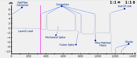
Experienced OTDR users will recognize reflective events for tester connectors, launch cords, connectors, mechanical splices, fusion splices, miss-matched fibers and the end of the link. And they will know that the little blips they see after the end of the link are ghosts, which are not real events to be concerned with.
But if you’re not a trace analysis expert, don’t worry. The OptiFiber® Pro also uses advanced logic to interpret the trace and provide an EventMap that characterizes the actual events. And faulty events are highlighted with red icons so you can locate your problem even faster.
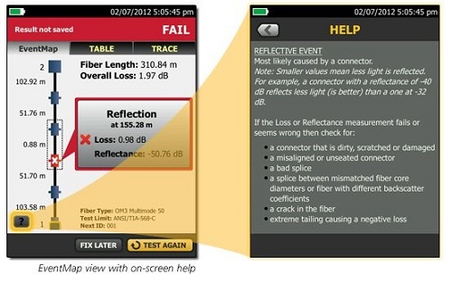
Accessible via a help icon in the bottom left of the EventMap, OptiFiber Pro even suggests corrective actions for resolving any problems. Now that definitely makes for an ultimate troubleshooting tool!
Recent Posts See All >
What Is Fiber Optics? A Guide
2024-03-20
Choosing Stranded vs. Solid Wire Cable
2024-03-06
What Is Return Loss?
2023-02-14
More General Posts See All >
What Is Fiber Optics? A Guide
2024-03-20
Choosing Stranded vs. Solid Wire Cable
2024-03-06
What Is the Right Way to Test an MPTL?
2023-08-22
Explore Our Products
OptiFiber® Pro OTDR Family


©2006-2021 Fluke Corporation。保留所有权利。
RM2011, 20/F, SCITECH Tower, 22 Jianguomenwai Avenue, Chaoyang District, Beijing, China
地址:北京市朝阳区建国门外大街22号赛特大厦20层2011室
联系电话:400-8103435
沪ICP备11037028号-15![]()